

What is multiplexing?

- Multiplexing or (muxing) - It is a processes combining multiple signals (analog or digital) for transmission over a single line or media.
- A common type of multiplexing combines several low-speed signals for transmission over a single high-speed connection.
Concept of Multiplexing
- As shown in figure multiplexer takes 4 input lines and diverts them to a single output line.
- The signal from 4 different devices is combined and carried by this single line.
- At the receiving side, a demultiplexer takes this signal from a single line and breaks it into the original signals and passes them to the 4 different receivers.

- Communication is possible over the air (radio frequency), using a physical media (cable), and light (optical fiber). All mediums are capable of multiplexing.
- When multiple senders try to send over a single medium, a device called Multiplexer divides the physical channel and allocates one to each.
- On the other end of communication, a De-multiplexer receives data from a single medium, identifies each, and sends to different receivers.
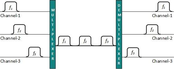
Frequency Division Multiplexing
- When the carrier is frequency, FDM is used. FDM is an analog technology. FDM divides the spectrum or carrier bandwidth in logical channels and allocates one user to each channel.
- Each user can use the channel frequency independently and has exclusive access of it. All channels are divided in such a way that they do not overlap with each other.
- It is used in the analogue signal, a multiplexing technique that uses different frequencies to combine multiple streams of data for transmission over a communications medium.
- FDM assigns a different carrier frequency to each data stream and then combines many modulated carrier frequencies for transmission.
- The carrier frequencies are separated by a sufficient bandwidth to accommodate the modulated signal.
- These ranges of bandwidth are the channels through which the different signals travel.
- Channels are separated by guard bands. Guard band is a frequency which is not used by either channel.
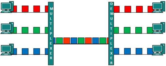
Time Division Multiplexing
- TDM is applied primarily on digital signals but can be applied on analog signals as well.
- In TDM the shared channel is divided among its user by means of time slot. Each user can transmit data within the provided time slot only.
- Digital signals are divided in frames, equivalent to time slot i.e. frame of an optimal size which can be transmitted in given time slot.
- A type of multiplexing that combines data streams by assigning each stream a different time slot in a set.
- TDM is designed for digital signals, which combining several low-rate channels into high-rate one. TDM repeatedly transmits a fixed sequence of time slots over a single transmission channel.
- Within T-Carrier systems, such as T-1 and T-3, TDM combines Pulse Code Modulated (PCM) streams created for each conversation or data stream.
- TDM, slots are further divided into Frames. In order to separate channels AND gates are used in a TDM receiver.
- TDM works in synchronized mode. Both ends, i.e.
- Multiplexer and De-multiplexer are timely synchronized and both switch to next channel simultaneously.
- When channel A transmits its frame at one end,the De-multiplexer provides media to channel A on the other end.
- As soon as the channel A’s time slot expires, this side switches to channel B.
- On the other end, the De-multiplexer works in a synchronized manner and provides media to channel B.
- Signals from different channels travel the path in interleaved manner.
Wavelength Division Multiplexing
- Light has different wavelength (colors). In fiber optic mode, multiple optical carrier signals are multiplexed into an optical fiber by using different wavelengths.
- It used in the analog signal, a type of multiplexing developed for use on optical fibre.
- The idea is the same: different signals on different frequencies are combined.
- However, the difference is that the frequencies are very high. WDM is the optical equivalent of FDM.
- The figure gives a conceptual view of a WSM multiplexer and demultiplexer. Very narrow bands of light from different sources combine to achieve a wider band of light. In the receiver, the signals separated by the demultiplexer.
- This is an analog multiplexing technique and is done conceptually in the same manner as FDM but uses light as signals.
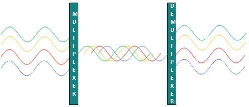
- Further, on each wavelength time division multiplexing can be incorporated to accommodate more data signals.
Code Division Multiplexing
- Multiple data signals can be transmitted over a single frequency by using Code Division Multiplexing.
- FDM divides the frequency in smaller channels but CDM allows its users to full bandwidth and transmit signals all the time using a unique code.
- CDM uses orthogonal codes to spread signals.
- Each station is assigned with a unique code, called chip. Signals travel with these codes independently, inside the whole bandwidth.
- The receiver knows in advance the chip code signal it has to receive.


Sure! Here's a short blog comment in English using your keyword FlareSolverr 2–3 times, naturally and without links or titlesThanks for the detailed post! I’ve been testing FlareSolverr lately for bypassing Cloudflare, and it’s working really well. FlareSolverr setup can be tricky at first, but once it's configured properly, it handles challenges smoothly. Anyone using FlareSolverr with scraping tools will definitely see better results."
ReplyDelete