Network Switching
- Switching is process to forward packets coming in from one port to a port leading towards the destination. When data comes on a port it is called ingress, and when data leaves a port or goes out it is called egress. A communication system may include number of switches and nodes. At broad level, switching can be divided into two major categories:
- The data is forwarded on behalf of forwarding tables. No previous handshaking is required and acknowledgements are optional.
- Before switching data to be forwarded to destination, there is a need to pre-establish circuit along the path between both endpoints.
- Data is then forwarded on that circuit. After the transfer is completed, circuits can be kept for future use or can be turned down immediately.
Circuit Switching
- When two nodes communicate with each other over a dedicated communication path, it is called circuit switching.
- There 'is a need of pre-specified route from which data will travels and no other data is permitted.In circuit switching, to transfer the data, circuit must be established so that the data transfer can take place.
- Circuits can be permanent or temporary. Applications which use circuit switching may have to go through three phases:
- Establish a circuit
- Transfer the data
- Disconnect the circuit
- Circuit switching was designed for voice applications. Telephone is the best suitable example of circuit switching.
- Before a user can make a call, a virtual path between caller and callee is established over the network.
Message Switching
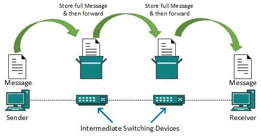
- This technique was somewhere in middle of circuit switching and packet switching. In message switching, the whole message is treated as a data unit and is switching / transferred in its entirety.
- A switch working on message switching, first receives the whole message and buffers it until there are resources available to transfer it to the next hop.
- If the next hop is not having enough resource to accommodate large size message, the message is stored and switch waits.
- This technique was considered substitute to circuit switching. As in circuit switching the whole path is blocked for two entities only. Message switching is replaced by packet switching. Message switching has the following drawbacks:
- Every switch in transit path needs enough storage to accommodate entire message.
- Because of store-and-forward technique and waits included until resources are available, message switching is very slow.
- Message switching was not a solution for streaming media and real-time applications.
Packet Switching
- Shortcomings of message switching gave birth to an idea of packet switching. The entire message is broken down into smaller chunks called packets.
- The switching information is added in the header of each packet and transmitted independently.
- It is easier for intermediate networking devices to store small size packets and they do not take much resources either on carrier path or in the internal memory of switches.
- Packet switching enhances line efficiency as packets from multiple applications can be multiplexed over the carrier.
- The internet uses packet switching technique. Packet switching enables the user to differentiate data streams based on priorities.
- Packets are stored and forwarded according to their priority to provide quality of service.
Data-link Layer Introduction
- Data Link Layer is second layer of OSI Layered Model. This layer is one of the most complicated layers and has complex functionalities and liabilities.
- Data link layer hides the details of underlying hardware and represents itself to upper layer as the medium to communicate.
- Data link layer works between two hosts which are directly connected in some sense. This direct connection could be point to point or broadcast.
- Systems on broadcast network are said to be on same link. The work of data link layer tends to get more complex when it is dealing with multiple hosts on single collision domain.
- Data link layer is responsible for converting data stream to signals bit by bit and to send that over the underlying hardware.
- At the receiving end, Data link layer picks up data from hardware which are in the form of electrical signals, assembles them in a recognizable frame format, and hands over to upper layer.
- Logical Link Control: It deals with protocols, flow-control, and error control
- Media Access Control: It deals with actual control of media
Functionality of Data-link Layer
- Data link layer does many tasks on behalf of upper layer. These are:
Framing
- Data-link layer takes packets from Network Layer and encapsulates them into Frames.Then, it sends each frame bit-by-bit on the hardware.
- At receiver’ end, data link layer picks up signals from hardware and assembles them into frames.
Addressing
- Data-link layer provides layer-2 hardware addressing mechanism. Hardware address is assumed to be unique on the link. It is encoded into hardware at the time of manufacturing.
Synchronization
- When data frames are sent on the link, both machines must be synchronized in order to transfer to take place.
Error Control
- Sometimes signals may have encountered problem in transition and the bits are flipped.These errors are detected and attempted to recover actual data bits.
- It also provides error reporting mechanism to the sender.
Flow Control
- Stations on same link may have different speed or capacity. Data-link layer ensures flow control that enables both machine to exchange data on same speed.
Multi-Access
- When host on the shared link tries to transfer the data, it has a high probability of collision.
- Data-link layer provides mechanism such as CSMA/CD to equip capability of accessing a shared media among multiple Systems.
Error Detection and Correction
- There are many reasons such as noise, cross-talk etc., which may help data to get corrupted during transmission.
- The upper layers work on some generalized view of network architecture and are not aware of actual hardware data processing.Hence, the upper layers expect error-free transmission between the systems.
- Most of the applications would not function expectantly if they receive erroneous data. Applications such as voice and video may not be that affected and with some errors they may still function well.
- Data-link layer uses some error control mechanism to ensure that frames (data bit streams) are transmitted with certain level of accuracy.
- But to understand how errors is controlled, it is essential to know what types of errors may occur.
Types of Errors
- There may be three types of errors:
Single bit error
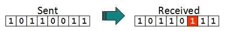
- In a frame, there is only one bit, anywhere though, which is corrupt.
Multiple bits error

- Frame is received with more than one bits in corrupted state.
Burst error
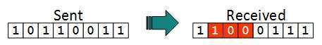
- Frame contains more than 1 consecutive bits corrupted.
- Error control mechanism may involve two possible ways:
- Error detection
- Error correction
Error Detection
- Errors in the received frames are detected by means of Parity Check and Cyclic Redundancy Check (CRC).
- In both cases, few extra bits are sent along with actual data to confirm that bits received at other end are same as they were sent.
- If the counter-check at receiver’ end fails, the bits are considered corrupted.
Parity Check
- One extra bit is sent along with the original bits to make number of 1s either even in case of even parity, or odd in case of odd parity.
- The sender while creating a frame counts the number of 1s in it. For example, if even parity is used and number of 1s is even then one bit with value 0 is added.
- This way number of 1s remains even.If the number of 1s is odd, to make it even a bit with value 1 is added.
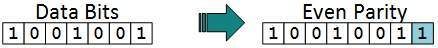
- The receiver simply counts the number of 1s in a frame. If the count of 1s is even and even parity is used, the frame is considered to be not-corrupted and is accepted.
- If the count of 1s is odd and odd parity is used, the frame is still not corrupted.
- If a single bit flips in transit, the receiver can detect it by counting the number of 1s.
- But when more than one bits are erroneous, then it is very hard for the receiver to detect the error.
Cyclic Redundancy Check (CRC)
- CRC is a different approach to detect if the received frame contains valid data. This technique involves binary division of the data bits being sent.
- The divisor is generated using polynomials. The sender performs a division operation on the bits being sent and calculates the remainder.
- Before sending the actual bits, the sender adds the remainder at the end of the actual bits.
- Actual data bits plus the remainder is called a code word. The sender transmits data bits as code words.
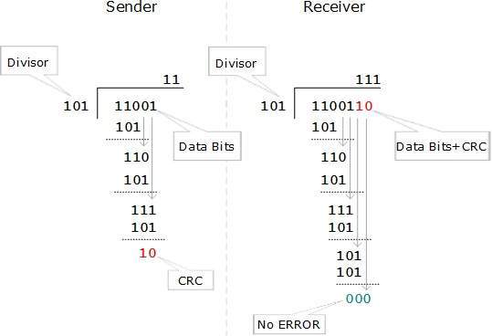
- At the other end, the receiver performs division operation on code words using the same CRC divisor.
- If the remainder contains all zeros the data bits are accepted, otherwise it is considered as there some data corruption occurred in transit.
Error Correction
In the digital world, error correction can be done in two ways:
Backward Error Correction - When the receiver detects an error in the data received, it requests back the sender to re transmit the data unit.
- When the receiver detects some error in the data received, it executes error-correcting code, which helps it to auto-recover and to correct some kinds of errors.
- The first one, Backward Error Correction, is simple and can only be efficiently used where re-transmitting is not expensive.
- For example, fiber optics. But in case of wireless transmission re-transmitting may cost too much. In the latter case, Forward Error Correction is used.
- To correct the error in data frame, the receiver must know exactly which bit in the frame is corrupted.
- To locate the bit in error, redundant bits are used as parity bits for error detection.For example, we take ASCII words (7 bits data), then there could be 8 kind of information we need: first seven bits to tell us which bit is error and one more bit to tell that there is no error.
- For m data bits, r redundant bits are used. r bits can provide 2r combinations of information. In m+r bit code word, there is possibility that the r bits themselves may get corrupted.
- So the number of r bits used must inform about m+r bit locations plus no-error information, i.e. m+r+1.
Data-link Control and Protocols
- Data-link layer is responsible for implementation of point-to-point flow and error control mechanism.
Flow Control
- When a data frame (Layer-2 data) is sent from one host to another over a single medium, it is required that the sender and receiver should work at the same speed.
- That is, sender sends at a speed on which the receiver can process and accept the data. What if the speed (hardware/software) of the sender or receiver differs? If sender is sending too fast the receiver may be overloaded, (swamped) and data may be lost.
Two types of mechanisms can be deployed to control the flow:
Stop and Wait
- This flow control mechanism forces the sender after transmitting a data frame to stop and wait until the acknowledgement of the data-frame sent is received.
Sliding Window
- In this flow control mechanism, both sender and receiver agree on the number of data-frames after which the acknowledgement should be sent.
- As we learnt, stop and wait flow control mechanism wastes resources, this protocol tries to make use of underlying resources as much as possible.
Error Control
- When data-frame is transmitted, there is a probability that data-frame may be lost in the transit or it is received corrupted. In both cases, the receiver does not receive the correct data-frame and sender does not know anything about any loss.
- In such case, both sender and receiver are equipped with some protocols which helps them to detect transit errors such as loss of data-frame. Hence, either the sender re-transmits the data-frame or the receiver may request to resend the previous data-frame.
Requirements for error control mechanism:
Error detection - - The sender and receiver, either both or any, must ascertain that there is some error in the transit.
- When the receiver receives a correct frame, it should acknowledge it.
- When the receiver receives a damaged frame or a duplicate frame, it sends a NACK back to the sender and the sender must re-transmit the correct frame.
- The sender maintains a clock and sets a timeout period.
- If an acknowledgement of a data-frame previously transmitted does not arrive before the timeout the sender re-transmits the frame, thinking that the frame or it’s acknowledgement is lost in transit.
There are three types of techniques available which Data-link layer may deploy to control the errors by Automatic Repeat Requests (ARQ):
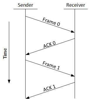
Stop-and-wait ARQ
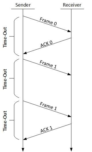
The following transition may occur in Stop-and-Wait ARQ:
- The sender maintains a timeout counter.
- When a frame is sent, the sender starts the timeout counter.
- If acknowledgement of frame comes in time, the sender transmits the next frame in queue.
- If acknowledgement does not come in time, the sender assumes that either the frame or its acknowledgement is lost in transit. Sender re-transmits the frame and starts the timeout counter.
- If a negative acknowledgement is received, the sender re-transmits the frame.
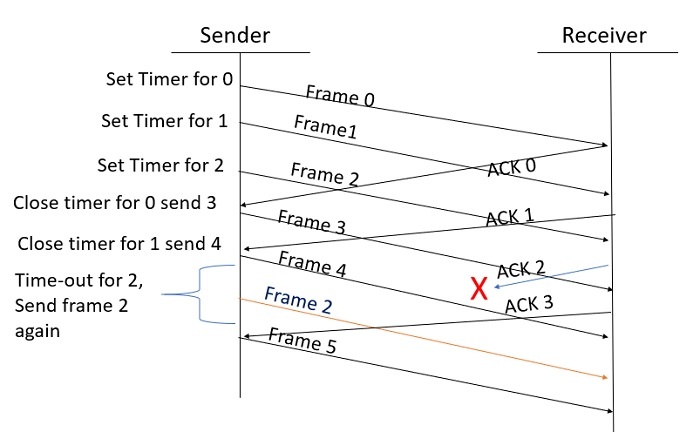
Go-Back-N ARQ
- Stop and wait ARQ mechanism does not utilize the resources at their best.When the acknowledgement is received, the sender sits idle and does nothing.
- In Go-Back-N ARQ method, both sender and receiver maintain a window.
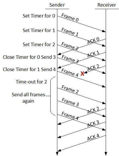
- The sending-window size enables the sender to send multiple frames without receiving the acknowledgement of the previous ones.
- The receiving-window enables the receiver to receive multiple frames and acknowledge them. The receiver keeps track of incoming frame’s sequence number.
- When the sender sends all the frames in window, it checks up to what sequence number it has received positive acknowledgement.
- If all frames are positively acknowledged, the sender sends next set of frames. If sender finds that it has received NACK or has not receive any ACK for a particular frame, it re-transmits all the frames after which it does not receive any positive ACK.
Selective Repeat ARQ
- In Go-back-N ARQ, it is assumed that the receiver does not have any buffer space for its window size and has to process each frame as it comes. This enforces the sender to re-transmit all the frames which are not acknowledged.
- In Selective-Repeat ARQ, the receiver while keeping track of sequence numbers, buffers the frames in memory and sends NACK for only frame which is missing or damaged.
- The sender in this case, sends only packet for which NACK is received.
Network Layer Introduction
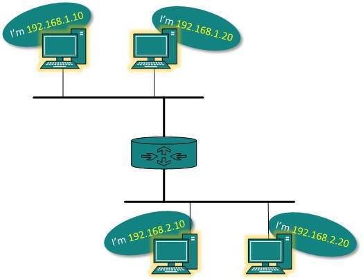
- Layer-3 in the OSI model is called Network layer. Network layer manages options pertaining to host and network addressing, managing sub-networks, and inter-networking.
- Network layer takes the responsibility for routing packets from source to destination within or outside a subnet.
- Two different subnet may have different addressing schemes or non-compatible addressing types. Same with protocols, two different subnet may be operating on different protocols which are not compatible with each other.
- Network layer has the responsibility to route the packets from source to destination, mapping different addressing schemes and protocols.
Layer-3 Functionalities
Devices which work on Network Layer mainly focus on routing. Routing may include various tasks aimed to achieve a single goal. These can be:
- Addressing devices and networks.
- Populating routing tables or static routes.
- Queuing incoming and outgoing data and then forwarding them according to quality of service constraints set for those packets.
- Internet-working between two different subnets.
- Delivering packets to destination with best efforts.
- Provides connection oriented and connection less mechanism.
Network Layer Features
With its standard functionalities, Layer 3 can provide various features as:
- Quality of service management
- Load balancing and link management
- Security
- Interrelation of different protocols and subnets with different schema.
- Different logical network design over the physical network design.
- L3 VPN and tunnels can be used to provide end to end dedicated connectivity.
- Internet protocol is widely respected and deployed Network Layer protocol which helps to communicate end to end devices over the internet.
- It comes in two flavors. IPv4 which has ruled the world for decades but now is running out of address space.
- IPv6 is created to replace IPv4 and hopefully mitigates limitations of IPv4 too.
Network Addressing
- Layer 3 network addressing is one of the major tasks of Network Layer.
- Network Addresses are always logical i.e. these are software based addresses which can be changed by appropriate configurations.
- A network address always points to host / node / server or it can represent a whole network.
- Network address is always configured on network interface card and is generally mapped by system with the MAC address (hardware address or layer-2 address) of the machine for Layer-2 communication.
- There are different kinds of network addresses in existence:
- IP
- IPX
- AppleTalk
We are discussing IP here as it is the only one we use in practice these days.
- IP addressing provides mechanism to differentiate between hosts and network. Because IP addresses are assigned in hierarchical manner, a host always resides under a specific network.
- The host which needs to communicate outside its subnet, needs to know destination network address, where the packet/data is to be sent.
- Hosts in different subnet need a mechanism to locate each other. This task can be done by DNS.
- DNS is a server which provides Layer-3 address of remote host mapped with its domain name or FQDN.
- When a host acquires the Layer-3 Address (IP Address) of the remote host, it forwards all its packet to its gateway.
- A gateway is a router equipped with all the information which leads to route packets to the destination host.
Routers take help of routing tables, which has the following information:
Method to reach the network- Routers upon receiving a forwarding request, forwards packet to its next hop (adjacent router) towards the destination.
- The next router on the path follows the same thing and eventually the data packet reaches its destination.
Network address can be of one of the following:
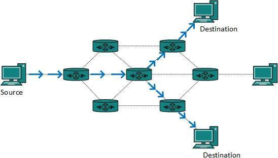
- Unicast (destined to one host)
- Multicast (destined to group)
- Broadcast (destined to all)
- Anycast (destined to nearest one)
- A router never forwards broadcast traffic by default. Multicast traffic uses special treatment as it is most a video stream or audio with highest priority.
- Anycast is just similar to unicast, except that the packets are delivered to the nearest destination when multiple destinations are available.
Network Layer Routing
- When a device has multiple paths to reach a destination, it always selects one path by preferring it over others. This selection process is termed as Routing.
- Routing is done by special network devices called routers or it can be done by means of software processes.
- The software based routers have limited functionality and limited scope.
- A router is always configured with some default route. A default route tells the router where to forward a packet if there is no route found for specific destination.
- In case there are multiple path existing to reach the same destination, router can make decision based on the following information:
- Hop Count
- Bandwidth
- Metric
- Prefix-length
- Delay
Routes can be statically configured or dynamically learnt. One route can be configured to be preferred over others.
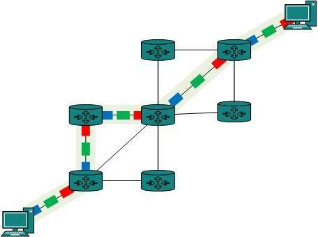
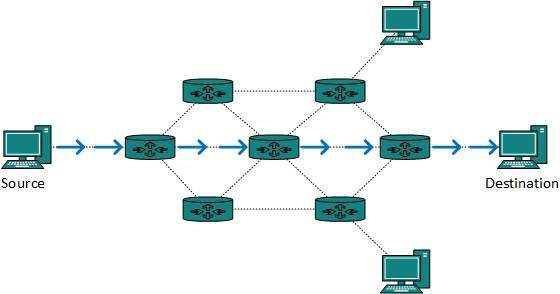
Unicast routing
- Most of the traffic on the internet and intranets known as unicast data or unicast traffic is sent with specified destination.
- Routing unicast data over the internet is called unicast routing. It is the simplest form of routing because the destination is already known.
- Hence the router just has to look up the routing table and forward the packet to next hop.
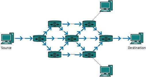
Broadcast routing
- By default, the broadcast packets are not routed and forwarded by the routers on any network. Routers create broadcast domains.
- But it can be configured to forward broadcasts in some special cases. A broadcast message is destined to all network devices.
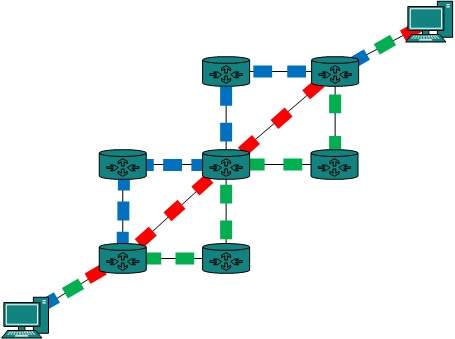
- Broadcast routing can be done in two ways (algorithm):
- A router creates a data packet and then sends it to each host one by one. In this case, the router creates multiple copies of single data packet with different destination addresses.
- All packets are sent as unicast but because they are sent to all, it simulates as if router is broadcasting.
- This method consumes lots of bandwidth and router must destination address of each node.
- Secondly, when router receives a packet that is to be broadcasted, it simply floods those packets out of all interfaces. All routers are configured in the same way.
- This method is easy on router's CPU but may cause the problem of duplicate packets received from peer routers.
- Reverse path forwarding is a technique, in which router knows in advance about its predecessor from where it should receive broadcast.
- This technique is used to detect and discard duplicates.
Multicast Routing
- Multicast routing is special case of broadcast routing with significance difference and challenges.
- In broadcast routing, packets are sent to all nodes even if they do not want it. But in Multicast routing, the data is sent to only nodes which wants to receive the packets.
- The router must know that there are nodes, which wish to receive multicast packets (or stream) then only it should forward.
- Multicast routing works spanning tree protocol to avoid looping.
- Multicast routing also uses reverse path Forwarding technique, to detect and discard duplicates and loops.
Anycast Routing
- Anycast packet forwarding is a mechanism where multiple hosts can have same logical address.
- When a packet destined to this logical address is received, it is sent to the host which is nearest in routing topology.
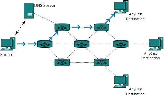
- Anycast routing is done with help of DNS server. Whenever an Anycast packet is received it is inquired with DNS to where to send it.
- DNS provides the IP address which is the nearest IP configured on it.
Unicast Routing Protocols
There are two kinds of routing protocols available to route unicast packets:
Distance Vector Routing Protocol
- Distance Vector is simple routing protocol which takes routing decision on the number of hops between source and destination.
- A route with less number of hops is considered as the best route. Every router advertises its set best routes to other routers.
- Ultimately, all routers build up their network topology based on the advertisements of their peer routers,
- For example Routing Information Protocol (RIP).
Link State Routing Protocol
- Link State protocol is slightly complicated protocol than Distance Vector. It takes into account the states of links of all the routers in a network.
- This technique helps routes build a common graph of the entire network.
- All routers then calculate their best path for routing purposes.for example, Open Shortest Path First (OSPF) and Intermediate System to Intermediate System (ISIS).
Multicast Routing Protocols
Unicast routing protocols use graphs while Multicast routing protocols use trees, i.e. spanning tree to avoid loops. The optimal tree is called shortest path spanning tree.
- DVMRP - Distance Vector Multicast Routing Protocol
- MOSPF - Multicast Open Shortest Path First
- CBT - Core Based Tree
- PIM - Protocol independent Multicast
Protocol Independent Multicast is commonly used now. It has two flavors:
PIM Dense Mode
- This mode uses source-based trees. It is used in dense environment such as LAN.
PIM Sparse Mode
- This mode uses shared trees. It is used in sparse environment such as WAN.
Routing Algorithms
The routing algorithms are as follows:
Flooding
- Flooding is simplest method packet forwarding. When a packet is received, the routers send it to all the interfaces except the one on which it was received.
- This creates too much burden on the network and lots of duplicate packets wandering in the network.
- Time to Live (TTL) can be used to avoid infinite looping of packets.
- There exists another approach for flooding, which is called Selective Flooding to reduce the overhead on the network. In this method, the router does not flood out on all the interfaces, but selective ones.
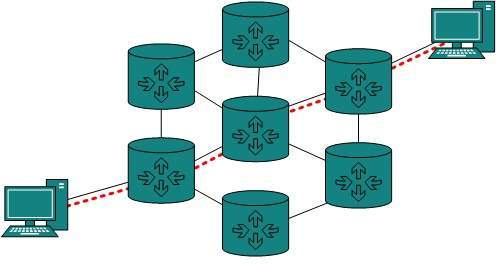
Shortest Path
- Routing decision in networks, are mostly taken on the basis of cost between source and destination. Hop count plays major role here.
- Shortest path is a technique which uses various algorithms to decide a path with minimum number of hops.
Common shortest path algorithms are:
- Dijkstra's algorithm
- Bellman Ford algorithm
- Floyd Warshall algorithm
Internetworking
- In real world scenario, networks under same administration are generally scattered geographically.
- There may exist requirement of connecting two different networks of same kind as well as of different kinds. Routing between two networks is called internetworking.
- Networks can be considered different based on various parameters such as, Protocol, topology, Layer-2 network and addressing scheme.
- In internetworking, routers have knowledge of each other’s address and addresses beyond them.
- They can be statically configured go on different network or they can learn by using internetworking routing protocol.
- Routing protocols which are used within an organization or administration are called Interior Gateway Protocols or IGP. RIP, OSPF are examples of IGP.
- Routing between different organizations or administrations may have Exterior Gateway Protocol, and there is only one EGP i.e. Border Gateway Protocol.
Tunneling
- If they are two geographically separate networks, which want to communicate with each other, they may deploy a dedicated line between or they have to pass their data through intermediate networks.
- Tunneling is a mechanism by which two or more same networks communicate with each other, by passing intermediate networking complexities.
- Tunneling is configured at both ends.
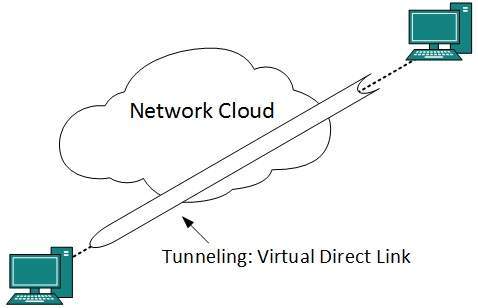
- When the data enters from one end of Tunnel, it is tagged.
- This tagged data is then routed inside the intermediate or transit network to reach the other end of Tunnel. When data exists the Tunnel its tag is removed and delivered to the other part of the network.
- Both ends seem as if they are directly connected and tagging makes data travel through transit network without any modifications.
Packet Fragmentation
- Most Ethernet segments have their maximum transmission unit (MTU) fixed to 1500 bytes.
- A data packet can have more or less packet length depending upon the application.
- Devices in the transit path also have their hardware and software capabilities which tell what amount of data that device can handle and what size of packet it can process.
- If the data packet size is less than or equal to the size of packet the transit network can handle, it is processed neutrally.
- If the packet is larger, it is broken into smaller pieces and then forwarded. This is called packet fragmentation.
- Each fragment contains the same destination and source address and routed through transit path easily. At the receiving end it is assembled again.
- If a packet with DF (don’t fragment) bit set to 1 comes to a router which can not handle the packet because of its length, the packet is dropped.
- When a packet is received by a router has its MF (more fragments) bit set to 1, the router then knows that it is a fragmented packet and parts of the original packet is on the way.
- If packet is fragmented too small, the overhead is increases. If the packet is fragmented too large, intermediate router may not be able to process it and it might get dropped.
Network Layer Protocols
- Every computer in a network has an IP address by which it can be uniquely identified and addressed. An IP address is Layer-3 (Network Layer) logical address.
- This address may change every time a computer restarts. A computer can have one IP at one instance of time and another IP at some different time.
Address Resolution Protocol(ARP)
- While communicating, a host needs Layer-2 (MAC) address of the destination machine which belongs to the same broadcast domain or network.
- A MAC address is physically burnt into the Network Interface Card (NIC) of a machine and it never changes.
- On the other hand, IP address on the public domain is rarely changed. If the NIC is changed in case of some fault, the MAC address also changes.
- This way, for Layer-2 communication to take place, a mapping between the two is required.
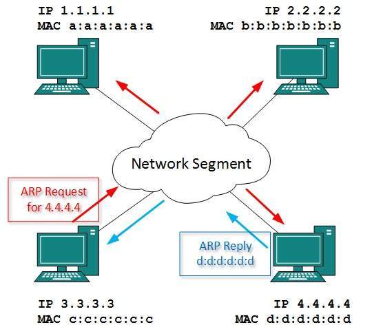
- To know the MAC address of remote host on a broadcast domain, a computer wishing to initiate communication sends out an ARP broadcast message asking, “Who has this IP address?” Because it is a broadcast, all hosts on the network segment (broadcast domain) receive this packet and process it.
- ARP packet contains the IP address of destination host, the sending host wishes to talk to. When a host receives an ARP packet destined to it, it replies back with its own MAC address.
- Once the host gets destination MAC address, it can communicate with remote host using Layer-2 link protocol.
- This MAC to IP mapping is saved into ARP cache of both sending and receiving hosts. Next time, if they require to communicate, they can directly refer to their respective ARP cache.
- Reverse ARP is a mechanism where host knows the MAC address of remote host but requires to know IP address to communicate.
Internet Control Message Protocol (ICMP)
- ICMP is network diagnostic and error reporting protocol. ICMP belongs to IP protocol suite and uses IP as carrier protocol.
- After constructing ICMP packet, it is encapsulated in IP packet. Because IP itself is a best-effort non-reliable protocol, so is ICMP.
- Any feedback about network is sent back to the originating host. If some error in the network occurs, it is reported by means of ICMP.
- ICMP contains dozens of diagnostic and error reporting messages.
- ICMP-echo and ICMP-echo-reply are the most commonly used ICMP messages to check the reach ability of end-to-end hosts.
- When a host receives an ICMP-echo request, it is bound to send back an ICMP-echo-reply. If there is any problem in the transit network, the ICMP will report that problem.
Internet Protocol Version 4 (IPv4)
- IPv4 is 32-bit addressing scheme used as TCP/IP host addressing mechanism. IP addressing enables every host on the TCP/IP network to be uniquely identifiable.
- IPv4 provides hierarchical addressing scheme which enables it to divide the network into sub-networks, each with well-defined number of hosts.
- IP addresses are divided into many categories:
- Class A - it uses first octet for network addresses and last three octets for host addressing
- Class B - it uses first two octets for network addresses and last two for host addressing
- Class C - it uses first three octets for network addresses and last one for host addressing
- Class D - it provides flat IP addressing scheme in contrast to hierarchical structure for above three.
- Class E - It is used as experimental.
- IPv4 also has well-defined address spaces to be used as private addresses (not routable on internet), and public addresses (provided by ISPs and are routable on internet).
- Though IP is not reliable one; it provides ‘Best-Effort-Delivery’ mechanism.
Internet Protocol Version 6 (IPv6)
- Exhaustion of IPv4 addresses gave birth to a next generation Internet Protocol version 6.
- IPv6 addresses its nodes with 128-bit wide address providing plenty of address space for future to be used on entire planet or beyond.
- IPv6 has introduced Anycast addressing but has removed the concept of broadcasting.
- IPv6 enables devices to self-acquire an IPv6 address and communicate within that subnet. This auto-configuration removes the dependability of Dynamic Host Configuration Protocol (DHCP) servers.
- This way, even if the DHCP server on that subnet is down, the hosts can communicate with each other.
- IPv6 provides new feature of IPv6 mobility. Mobile IPv6 equipped machines can roam around without the need of changing their IP addresses.
- IPv6 is still in transition phase and is expected to replace IPv4 completely in coming years. At present, there are few networks which are running on IPv6.
- There are some transition mechanisms available for IPv6 enabled networks to speak and roam around different networks easily on IPv4. These are:
- Dual stack implementation
- Tunneling
- NAT-PT
Transport Layer Introduction
- Next Layer in OSI Model is recognized as Transport Layer (Layer-4). All modules and procedures pertaining to transportation of data or data stream are categorized into this layer.
- As all other layers, this layer communicates with its peer Transport layer of the remote host.
- Transport layer offers peer-to-peer and end-to-end connection between two processes on remote hosts.
- Transport layer takes data from upper layer (i.e. Application layer) and then breaks it into smaller size segments, numbers each byte, and hands over to lower layer (Network Layer) for delivery.
Functions
- This Layer is the first one which breaks the information data, supplied by Application layer in to smaller units called segments.
- It numbers every byte in the segment and maintains their accounting.
- This layer ensures that data must be received in the same sequence in which it was sent.
- This layer provides end-to-end delivery of data between hosts which may or may not belong to the same subnet.
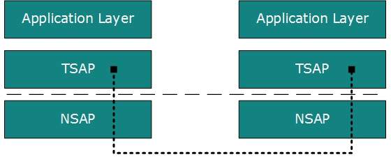
- All server processes intend to communicate over the network are equipped with well-known Transport Service Access Points (TSAPs) also known as port numbers.
End-to-End Communication
- A process on one host identifies its peer host on remote network by means of TSAPs, also known as Port numbers.
- TSAPs are very well defined and a process which is trying to communicate with its peer knows this in advance.
- For example, when a DHCP client wants to communicate with remote DHCP server, it always requests on port number 67.
- When a DNS client wants to communicate with remote DNS server, it always requests on port number 53 (UDP).
The two main Transport layer protocols are:
Transmission Control Protocol
- It provides reliable communication between two hosts.
User Datagram Protocol
- It provides unreliable communication between two hosts.
Transmission Control Protocol
- The transmission Control Protocol (TCP) is one of the most important protocols of Internet Protocols suite. It is most widely used protocol for data transmission in communication network such as internet.
Features
- TCP is reliable protocol. That is, the receiver always sends either positive or negative acknowledgement about the data packet to the sender, so that the sender always has bright clue about whether the data packet is reached the destination or it needs to resend it.
- TCP ensures that the data reaches intended destination in the same order it was sent.
- TCP is connection oriented. TCP requires that connection between two remote points be established before sending actual data.
- TCP provides error-checking and recovery mechanism.
- TCP provides end-to-end communication.
- TCP provides flow control and quality of service.
- TCP operates in Client/Server point-to-point mode.
- TCP provides full duplex server, i.e. it can perform roles of both receiver and sender.
Header
The length of TCP header is minimum 20 bytes long and maximum 60 bytes.
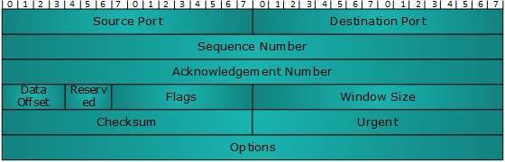
- Source Port (16-bits) - It identifies source port of the application process on the sending device.
- Destination Port (16-bits) - It identifies destination port of the application process on the receiving device.
- Sequence Number (32-bits) - Sequence number of data bytes of a segment in a session.
- Acknowledgement Number (32-bits) - When ACK flag is set, this number contains the next sequence number of the data byte expected and works as acknowledgement of the previous data received.
- Data Offset (4-bits) - This field implies both, the size of TCP header (32-bit words) and the offset of data in current packet in the whole TCP segment.
- Reserved (3-bits) - Reserved for future use and all are set zero by default.
- Flags (1-bit each)
- NS - Nonce Sum bit is used by Explicit Congestion Notification signaling process.
- CWR - When a host receives packet with ECE bit set, it sets Congestion Windows Reduced to acknowledge that ECE received.
- If SYN bit is clear to 0, then ECE means that the IP packet has its CE (congestion experience) bit set.ECE -It has two meanings:
- If SYN bit is set to 1, ECE means that the device is ECT capable.
- URG - It indicates that Urgent Pointer field has significant data and should be processed.
- ACK - It indicates that Acknowledgement field has significance. If ACK is cleared to 0, it indicates that packet does not contain any acknowledgement.
- PSH - When set, it is a request to the receiving station to PUSH data (as soon as it comes) to the receiving application without buffering it.
- It is used to refuse an incoming connection.RST - Reset flag has the following features:
- It is used to reject a segment.
- It is used to restart a connection.
- SYN - This flag is used to set up a connection between hosts.
- FIN - This flag is used to release a connection and no more data is exchanged thereafter. Because packets with SYN and FIN flags have sequence numbers, they are processed in correct order.
- Windows Size - This field is used for flow control between two stations and indicates the amount of buffer (in bytes) the receiver has allocated for a segment, i.e. how much data is the receiver expecting.
- Checksum - This field contains the checksum of Header, Data and Pseudo Headers.
- Urgent Pointer - It points to the urgent data byte if URG flag is set to 1.
- Options - It facilitates additional options which are not covered by the regular header. Option field is always described in 32-bit words. If this field contains data less than 32-bit, padding is used to cover the remaining bits to reach 32-bit boundary.
Connection Management
- TCP communication works in Server/Client model. The client initiates the connection and the server either accepts or rejects it.
- Three-way handshaking is used for connection management.
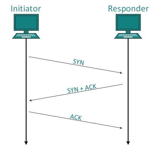
Establishment
- Client initiates the connection and sends the segment with a Sequence number. Server acknowledges it back with its own Sequence number and ACK of client’s segment which is one more than client’s Sequence number.
- Client after receiving ACK of its segment sends an acknowledgement of Server’s response.
Release
- Either of server and client can send TCP segment with FIN flag set to 1.
- When the receiving end responds it back by acknowledging FIN, that direction of TCP communication is closed and connection is released.
Bandwidth Management
- TCP uses the concept of window size to accommodate the need of Bandwidth management. Window size tells the sender at the remote end, the number of data byte segments the receiver at this end can receive.
- TCP uses slow start phase by using window size 1 and increases the window size exponentially after each successful communication.
- For example, the client uses windows size 2 and sends 2 bytes of data.
- When the acknowledgement of this segment received the windows size is doubled to 4 and next sent the segment sent will be 4 data bytes long.
- When the acknowledgement of 4-byte data segment is received, the client sets windows size to 8 and so on.
- If an acknowledgement is missed, i.e. data lost in transit network or it received NACK, then the window size is reduced to half and slow start phase starts again.
Error Control &and Flow Control
- TCP uses port numbers to know what application process it needs to handover the data segment. Along with that, it uses sequence numbers to synchronize itself with the remote host.
- All data segments are sent and received with sequence numbers. The Sender knows which last data segment was received by the Receiver when it gets ACK.
- The Receiver knows about the last segment sent by the Sender by referring to the sequence number of recently received packet.
- If the sequence number of a segment recently received does not match with the sequence number the receiver was expecting, then it is discarded and NACK is sent back.
- If two segments arrive with the same sequence number, the TCP timestamp value is compared to make a decision.
Multiplexing
- The technique to combine two or more data streams in one session is called Multiplexing.
- When a TCP client initializes a connection with Server, it always refers to a well-defined port number which indicates the application process.
- The client itself uses a randomly generated port number from private port number pools.
- Using TCP Multiplexing, a client can communicate with a number of different application process in a single session.
- For example, a client requests a web page which in turn contains different types of data (HTTP, SMTP, FTP etc.) the TCP session timeout is increased and the session is kept open for longer time so that the three-way handshake overhead can be avoided.
- This enables the client system to receive multiple connection over single virtual connection.
- These virtual connections are not good for Servers if the timeout is too long.
Congestion Control
When large amount of data is fed to system which is not capable of handling it, congestion occurs. TCP controls congestion by means of Window mechanism. TCP sets a window size telling the other end how much data segment to send. TCP may use three algorithms for congestion control:
- Additive increase, Multiplicative Decrease
- Slow Start
- Timeout React
Timer Management
TCP uses different types of timer to control and management various tasks:
Keep-alive timer:
- This timer is used to check the integrity and validity of a connection.
- When keep-alive time expires, the host sends a probe to check if the connection still exists.
Re-transmission timer:
- This timer maintains stateful session of data sent.
- If the acknowledgement of sent data does not receive within the Re-transmission time, the data segment is sent again.
Persist timer:
- TCP session can be paused by either host by sending Window Size 0.
- To resume the session a host needs to send Window Size with some larger value.
- If this segment never reaches the other end, both ends may wait for each other for infinite time.
- When the Persist timer expires, the host re-sends its window size to let the other end know.
- Persist Timer helps avoid deadlocks in communication.
Timed-Wait:
- After releasing a connection, either of the hosts waits for a Timed-Wait time to terminate the connection completely.
- This is in order to make sure that the other end has received the acknowledgement of its connection termination request.
- Timed-out can be a maximum of 240 seconds (4 minutes).
Crash Recovery
- TCP is very reliable protocol. It provides sequence number to each of byte sent in segment. It provides the feedback mechanism i.e. when a host receives a packet, it is bound to ACK that packet having the next sequence number expected (if it is not the last segment).
- When a TCP Server crashes mid-way communication and re-starts its process it sends TPDU broadcast to all its hosts. The hosts can then send the last data segment which was never unacknowledged and carry onwards.
User Datagram Protocol
- The User Datagram Protocol (UDP) is simplest Transport Layer communication protocol available of the TCP/IP protocol suite. It involves minimum amount of communication mechanism.
- UDP is said to be an unreliable transport protocol but it uses IP services which provides best effort delivery mechanism.
- In UDP, the receiver does not generate an acknowledgement of packet received and in turn, the sender does not wait for any acknowledgement of packet sent.
- This shortcoming makes this protocol unreliable as well as easier on processing.
Requirement of UDP
- A question may arise, why do we need an unreliable protocol to transport the data? We deploy UDP where the acknowledgement packets share significant amount of bandwidth along with the actual data.
- For example, in case of video streaming, thousands of packets are forwarded towards its users. Acknowledging all the packets is troublesome and may contain huge amount of bandwidth wastage.
- The best delivery mechanism of underlying IP protocol ensures best efforts to deliver its packets, but even if some packets in video streaming get lost, the impact is not calamitous and can be ignored easily.
- Loss of few packets in video and voice traffic sometimes goes unnoticed.
Features of UDP
- UDP is used when acknowledgement of data does not hold any significance.
- UDP is good protocol for data flowing in one direction.
- UDP is simple and suitable for query based communications.
- UDP is not connection oriented.
- UDP does not provide congestion control mechanism.
- UDP does not guarantee ordered delivery of data.
- UDP is stateless.
- UDP is suitable protocol for streaming applications such as VoIP, multimedia streaming.
UDP Header
- UDP header is as simple as its function.
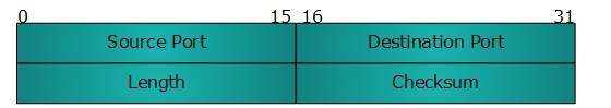
UDP header contains four main parameters:
Source Port -
- This 16 bits information is used to identify the source port of the packet.
- This 16 bits information, is used identify application level service on destination machine.
- Length field specifies the entire length of UDP packet (including header). It is 16-bits field and minimum value is 8-byte, i.e. the size of UDP header itself.
- This field stores the checksum value generated by the sender before sending.
- IPv4 has this field as optional so when checksum field does not contain any value it is made 0 and all its bits are set to zero.
UDP application
- Domain Name Services
- Simple Network Management Protocol
- Trivial File Transfer Protocol
- Routing Information Protocol
- Kerberos
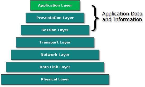
Application Layer Introduction
- Application layer is the top most layer in OSI and TCP/IP layered model. This layer exists in both layered Models because of its significance, of interacting with user and user applications.
- This layer is for applications which are involved in communication system.
- A user may or may not directly interacts with the applications. Application layer is where the actual communication is initiated and reflects.
- Because this layer is on the top of the layer stack, it does not serve any other layers. Application layer takes the help of Transport and all layers below it to communicate or transfer its data to the remote host.
- When an application layer protocol wants to communicate with its peer application layer protocol on remote host, it hands over the data or information to the Transport layer. The transport layer does the rest with the help of all the layers below it.
- There’is an ambiguity in understanding Application Layer and its protocol. Not every user application can be put into Application Layer. except those applications which interact with the communication system. For example, designing software or text-editor cannot be considered as application layer programs.
- On the other hand, when we use a Web Browser, which is actually using Hyper Text Transfer Protocol (HTTP) to interact with the network. HTTP is Application Layer protocol.
- Another example is File Transfer Protocol, which helps a user to transfer text based or binary files across the network.
- A user can use this protocol in either GUI based software like FileZilla or CuteFTP and the same user can use FTP in Command Line mode.
- Hence, irrespective of which software you use, it is the protocol which is considered at Application Layer used by that software. DNS is a protocol which helps user application protocols such as HTTP to accomplish its work.
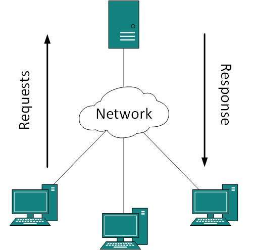
Client Server Model
- Peer-to-peer: Both remote processes are executing at same level and they exchange data using some shared resource.
- Client-Server: One remote process acts as a Client and requests some resource from another application process acting as Server.
In client-server model, any process can act as Server or Client. It is not the type of machine, size of the machine, or its computing power which makes it server; it is the ability of serving request that makes a machine a server.
- A system can act as Server and Client simultaneously. That is, one process is acting as Server and another is acting as a client.
- This may also happen that both client and server processes reside on the same machine.
Communication
Two processes in client-server model can interact in various ways:
- Sockets
- Remote Procedure Calls (RPC)
Sockets
- In this paradigm, the process acting as Server opens a socket using a well-known (or known by client) port and waits until some client request comes.
- The second process acting as a Client also opens a socket but instead of waiting for an incoming request, the client processes ‘requests first’.
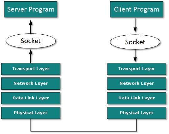
- When the request is reached to server, it is served. It can either be an information sharing or resource request.
Remote Procedure Call
This is a mechanism where one process interacts with another by means of procedure calls. One process (client) calls the procedure lying on remote host. The process on remote host is said to be Server. Both processes are allocated stubs. This communication happens in the following way:
- The client process calls the client stub. It passes all the parameters pertaining to program local to it.
- All parameters are then packed (marshalled) and a system call is made to send them to other side of the network.
- Kernel sends the data over the network and the other end receives it.
- The remote host passes data to the server stub where it is unmarshalled.
- The parameters are passed to the procedure and the procedure is then executed.
- The result is sent back to the client in the same manner.
Application Protocols
There are several protocols which work for users in Application Layer. Application layer protocols can be broadly divided into two categories:
- Protocols which are used by users.For email for example, eMail.
- Protocols which help and support protocols used by users.For example DNS.
Few of Application layer protocols are described below:
Domain Name System
- The Domain Name System (DNS) works on Client Server model. It uses UDP protocol for transport layer communication.
- DNS uses hierarchical domain based naming scheme. The DNS server is configured with Fully Qualified Domain Names (FQDN) and email addresses mapped with their respective Internet Protocol addresses.
- A DNS server is requested with FQDN and it responds back with the IP address mapped with it. DNS uses UDP port 53.
Simple Mail Transfer Protocol
- The Simple Mail Transfer Protocol (SMTP) is used to transfer electronic mail from one user to another. This task is done by means of email client software (User Agents) the user is using.
- User Agents help the user to type and format the email and store it until internet is available. When an email is submitted to send, the sending process is handled by Message Transfer Agent which is normally comes inbuilt in email client software.
- Message Transfer Agent uses SMTP to forward the email to another Message Transfer Agent (Server side).
- While SMTP is used by end user to only send the emails, the Servers normally use SMTP to send as well as receive emails. SMTP uses TCP port number 25 and 587.
- Client software uses Internet Message Access Protocol (IMAP) or POP protocols to receive emails.
File Transfer Protocol
- The File Transfer Protocol (FTP) is the most widely used protocol for file transfer over the network. FTP uses TCP/IP for communication and it works on TCP port 21.
- FTP works on Client/Server Model where a client requests file from Server and server sends requested resource back to the client.
- FTP uses out-of-band controlling i.e. FTP uses TCP port 20 for exchanging controlling information and the actual data is sent over TCP port 21.
- The client requests the server for a file. When the server receives a request for a file, it opens a TCP connection for the client and transfers the file.
- After the transfer is complete, the server closes the connection. For a second file, client requests again and the server reopens a new TCP connection.
Post Office Protocol (POP)
- The Post Office Protocol version 3 (POP 3) is a simple mail retrieval protocol used by User Agents (client email software) to retrieve mails from mail server.
- When a client needs to retrieve mails from server, it opens a connection with the server on TCP port 110.
- User can then access his mails and download them to the local computer.
- POP3 works in two modes. The most common mode the delete mode, is to delete the emails from remote server after they are downloaded to local machines.
- The second mode, the keep mode, does not delete the email from mail server and gives the user an option to access mails later on mail server.
Hyper Text Transfer Protocol (HTTP)
- The Hyper Text Transfer Protocol (HTTP) is the foundation of World Wide Web. Hypertext is well organized documentation system which uses hyperlinks to link the pages in the text documents.
- HTTP works on client server model. When a user wants to access any HTTP page on the internet, the client machine at user end initiates a TCP connection to server on port 80.
- When the server accepts the client request, the client is authorized to access web pages.
- To access the web pages, a client normally uses web browsers, who are responsible for initiating, maintaining, and closing TCP connections.
- HTTP is a stateless protocol, which means the Server maintains no information about earlier requests by clients.
HTTP versions
- HTTP 1.0 uses non persistent HTTP. At most one object can be sent over a single TCP connection.
- HTTP 1.1 uses persistent HTTP. In this version, multiple objects can be sent over a single TCP connection.
Network Services
- Computer systems and computerized systems help human beings to work efficiently and explore the unthinkable.
- When these devices are connected together to form a network, the capabilities are enhanced multiple-times. Some basic services computer network can offer are.
Directory Services
These services are mapping between name and its value, which can be variable value or fixed. This software system helps to store the information, organize it, and provides various means of accessing it.
Accounting
- In an organization, a number of users have their user names and passwords mapped to them.
- Directory Services provide means of storing this information in cryptic form and make available when requested.
Authentication &and Authorization
- User credentials are checked to authenticate a user at the time of login and/or periodically. User accounts can be set into hierarchical structure and their access to resources can be controlled using authorization schemes.
Domain Name Services
- DNS is widely used and one of the essential services on which internet works. This system maps IP addresses to domain names, which are easier to remember and recall than IP addresses.
- Because network operates with the help of IP addresses and humans tend to remember website names, the DNS provides website’s IP address which is mapped to its name from the back-end on the request of a website name from the user.
File Services
File services include sharing and transferring files over the network.
File Sharing
- One of the reason which gave birth to networking was file sharing. File sharing enables its users to share their data with other users.
- User can upload the file to a specific server, which is accessible by all intended users. As an alternative, user can make its file shared on its own computer and provides access to intended users.
File Transfer
- This is an activity to copy or move file from one computer to another computer or to multiple computers, with help of underlying network.
- Network enables its user to locate other users in the network and transfers files.
Communication Services
Email
- Electronic mail is a communication method and something a computer user cannot work without. This is the basis of today’s internet features.
- Email system has one or more email servers. All its users are provided with unique IDs.
- When a user sends email to other user, it is actually transferred between users with help of email server.
Social Networking
- Recent technologies have made technical life social. The computer savvy peoples, can find other known peoples or friends, can connect with them, and can share thoughts, pictures, and videos.
Internet Chat
- Internet chat provides instant text transfer services between two hosts. Two or more people can communicate with each other using text based Internet Relay Chat services. These days, voice chat and video chat are very common.
Discussion Boards
- Discussion boards provide a mechanism to connect multiple peoples with same interests.It enables the users to put queries, questions, suggestions etc. which can be seen by all other users. Other may respond as well.
Remote Access
- This service enables user to access the data residing on the remote computer. This feature is known as Remote desktop. This can be done via some remote device, e.g. mobile phone or home computer.
Application Services
These are nothing but providing network based services to the users such as web services, database managing, and resource sharing.
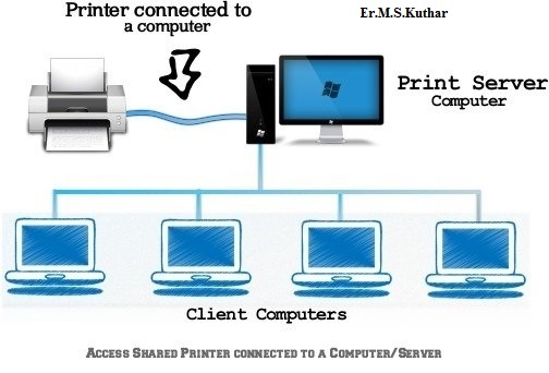
Resource Sharing
- To use resources efficiently and economically, network provides a mean to share them. This may include Servers, Printers, and Storage Media etc.
Databases
- This application service is one of the most important services. It stores data and information, processes it, and enables the users to retrieve it efficiently by using queries. Databases help organizations to make decisions based on statistics.
Web Services
- World Wide Web has become the synonym for internet.It is used to connect to the internet, and access files and information services provided by the internet servers.