

Data Communication Overview
- A system of interconnected computers and computerized peripherals such as printers is called computer network. This interconnection among computers facilitates information sharing among them. Computers may connect to each other by either wired or wireless media.
Classification of Computer Networks
Computer networks are classified based on various factors.They includes:
- Geographical span
- Inter-connectivity
- Administration
- Architecture
Geographical Span
Geographically a network can be seen in one of the following categories:
- It may be spanned across your table, among Bluetooth enabled devices,. Ranging not more than few meters.
- It may be spanned across a whole building, including intermediate devices to connect all floors.
- It may be spanned across a whole city.
- It may be spanned across multiple cities or provinces.
- It may be one network covering whole world.
Inter-Connectivity
Components of a network can be connected to each other differently in some fashion. By connectedness we mean either logically , physically , or both ways.
- Every single device can be connected to every other device on network, making the network mesh.
- All devices can be connected to a single medium but geographically disconnected, created bus like structure.
- Each device is connected to its left and right peers only, creating linear structure.
- All devices connected together with a single device, creating star like structure.
- All devices connected arbitrarily using all previous ways to connect each other, resulting in a hybrid structure.
Administration
- From an administrator’s point of view, a network can be private network which belongs a single autonomous system and cannot be accessed outside its physical or logical domain.A network can be public which is accessed by all.
Network Architecture
Computer networks can be discriminated into various types such as Client-Server,peer-to-peer or hybrid, depending upon its architecture.- There can be one or more systems acting as Server. Other being Client, requests the Server to serve requests.Server takes and processes request on behalf of Clients.
- Two systems can be connected Point-to-Point, or in back-to-back fashion. They both reside at the same level and called peers.
- There can be hybrid network which involves network architecture of both the above types.
Network Applications
Computer systems and peripherals are connected to form a network.They provide numerous advantages:
- Resource sharing such as printers and storage devices
- Exchange of information by means of e-Mails and FTP
- Information sharing by using Web or Internet
- Interaction with other users using dynamic web pages
- IP phones
- Video conferences
- Parallel computing
- Instant messaging
Computer Network Types
- Generally, networks are distinguished based on their geographical span. A network can be as small as distance between your mobile phone and its Bluetooth headphone and as large as the internet itself, covering the whole geographical world,
Personal Area Network(PAN)
- A Personal Area Network (PAN) is smallest network which is very personal to a user. This may include Bluetooth enabled devices or infra-red enabled devices.
- PAN has connectivity range up to 10 meters. PAN may include wireless computer keyboard and mouse, Bluetooth enabled headphones, wireless printers and TV remotes.
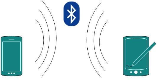
- For example, Piconet is Bluetooth-enabled Personal Area Network which may contain up to 8 devices connected together in a master-slave fashion.
Local Area Network
- A computer network spanned inside a building and operated under single administrative system is generally termed as Local Area Network (LAN). Usually,LAN covers an organization’ offices, schools, colleges or universities. Number of systems connected in LAN may vary from as least as two to as much as 16 million.
- LAN provides a useful way of sharing the resources between end users.The resources such as printers, file servers, scanners, and internet are easily sharable among computers.
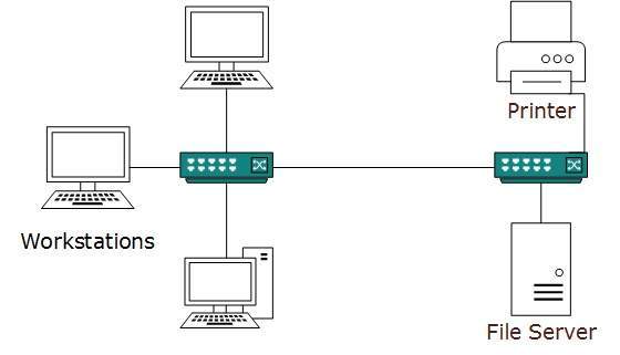
- LANs are composed of inexpensive networking and routing equipment. It may contains local servers serving file storage and other locally shared applications.
- It mostly operates on private IP addresses and does not involve heavy routing. LAN works under its own local domain and controlled centrally.
- LAN uses either Ethernet or Token-ring technology. Ethernet is most widely employed LAN technology and uses Star topology, while Token-ring is rarely seen.
- LAN can be wired,wireless, or in both forms at once.
Metropolitan Area Network
- The Metropolitan Area Network (MAN) generally expands throughout a city such as cable TV network. It can be in the form of Ethernet,Token-ring, ATM, or Fiber Distributed Data Interface (FDDI).
- Metro Ethernet is a service which is provided by ISPs. This service enables its users to expand their Local Area Networks.
- For example, MAN can help an organization to connect all of its offices in a city.
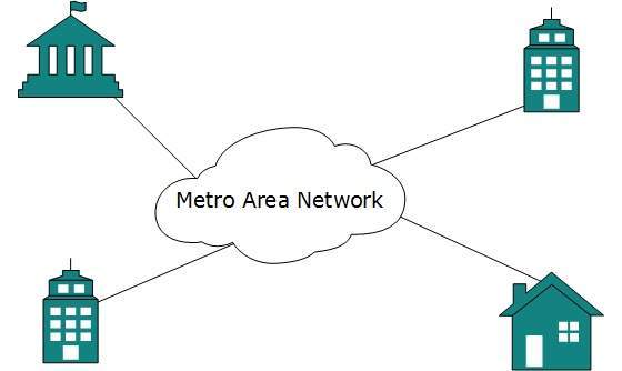
- Backbone of MAN is high-capacity and high-speed fiber optics. MAN works in between Local Area Network and Wide Area Network. MAN provides uplink for LANs to WANs or internet.
Wide Area Network
- As the name suggests,the Wide Area Network (WAN) covers a wide area which may span across provinces and even a whole country.
- Generally, telecommunication networks are Wide Area Network.
- These networks provide connectivity to MANs and LANs. Since they are equipped with very high speed backbone, WANs use very expensive network equipment.
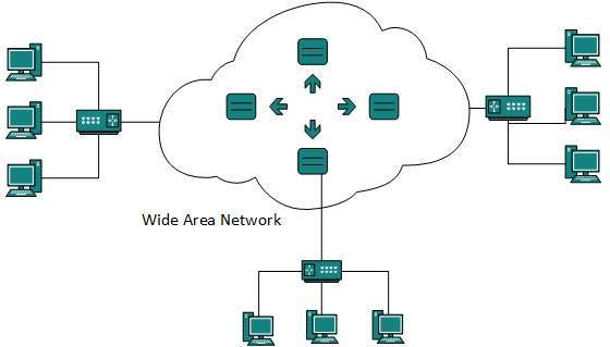
- WAN may use advanced technologies such as Asynchronous Transfer Mode (ATM), Frame Relay, and Synchronous Optical Network (SONET). WAN may be managed by multiple administration.
Internetwork
- A network of networks is called an internetwork, or simply the internet. It is the largest network in existence on this planet.
- The internet hugely connects all WANs and it can have connection to LANs and Home networks.
- Internet uses TCP/IP protocol suite and uses IP as its addressing protocol. Present day, Internet is widely implemented using IPv4. Because of shortage of address spaces, it is gradually migrating from IPv4 to IPv6.
- Internet enables its users to share and access enormous amount of information worldwide. It uses WWW, FTP, email services, audio and video streaming etc. At huge level, internet works on Client-Server model.
- Internet uses very high speed backbone of fiber optics. To inter-connect various continents, fibers are laid under sea known to us as submarine communication cable.
- Internet is widely deployed on World Wide Web services using HTML linked pages and is accessible by client software known as Web Browsers.
- When a user requests a page using some web browser located on some Web Server anywhere in the world, the Web Server responds with the proper HTML page. The communication delay is very low.
Internet is serving many proposes and is involved in many aspects of life. Some of them are:
- Web sites
- Instant Messaging
- Blogging
- Social Media
- Marketing
- Networking
- Resource Sharing
- Audio and Video Streaming
Network LAN Technologies
Let us go through various LAN technologies in brief:
Ethernet
- Ethernet is a widely deployed LAN technology.This technology was invented by Bob Metcalfe and D.R. Boggs in the year 1970. It was standardized in IEEE 802.3 in 1980.
- Ethernet shares media. Network which uses shared media has high probability of data collision.
- Ethernet uses Carrier Sense Multi Access/Collision Detection (CSMA/CD) technology to detect collisions.
- On the occurrence of collision in Ethernet, all its hosts roll back, wait for some random amount of time, and then re-transmit the data.
- Ethernet connector is,network interface card equipped with 48-bits MAC address. This helps other Ethernet devices to identify and communicate with remote devices in Ethernet.
- Traditional Ethernet uses 10BASE-T specifications.The number 10 depicts 10MBPS speed, BASE stands for baseband, and T stands for Thick Ethernet.
- 10BASE-T Ethernet provides transmission speed up to 10MBPS and uses coaxial cable or Cat-5 twisted pair cable with RJ-5 connector.
- Ethernet follows star topology with segment length up to 100 meters. All devices are connected to a hub/switch in a star fashion.
Fast-Ethernet
- To encompass need of fast emerging software and hardware technologies, Ethernet extends itself as Fast-Ethernet.
- It can run on UTP, Optical Fiber, and wirelessly too. It can provide speed up to 100 MBPS.
- This standard is named as 100BASE-T in IEEE 803.2 using Cat-5 twisted pair cable. It uses CSMA/CD technique for wired media sharing among the Ethernet hosts and CSMA/CA (CA stands for Collision Avoidance) technique for wireless Ethernet LAN.
- Fast Ethernet on fiber is defined under 100BASE-FX standard which provides speed up to 100 MBPS on fiber.
- Ethernet over fiber can be extended up to 100 meters in half-duplex mode and can reach maximum of 2000 meters in full-duplex over multi-mode fibers.
Giga-Ethernet
- After being introduced in 1995, Fast-Ethernet could enjoy its high speed status only for 3 years till Giga-Ethernet introduced. Giga-Ethernet provides speed up to 1000 mbits/seconds.
- IEEE802.3ab standardize Giga-Ethernet over UTP using Cat-5, Cat-5e and Cat-6 cables. IEEE802.3ah defines Giga-Ethernet over Fiber.
Virtual LAN
- LAN uses Ethernet which in turn works on shared media. Shared media in Ethernet create one single Broadcast domain and one single Collision domain.
- Introduction of switches to Ethernet has removed single collision domain issue and each device connected to switch works in its separate collision domain. But even Switches cannot divide a network into separate Broadcast domains.
- Virtual LAN is a solution to divide a single Broadcast domain into multiple Broadcast domains. Host in one VLAN cannot speak to a host in another. By default, all hosts are placed into the same VLAN.
- In this diagram, different VLANs are depicted in different color codes. Hosts in one VLAN, even if connected on the same Switch cannot see or speak to other hosts in different VLANs.
- VLAN is Layer-2 technology which works closely on Ethernet. To route packets between two different VLANs a Layer-3 device such as Router is required.
Computer Network Topologies
- A Network Topology is the arrangement with which computer systems or network devices are connected to each other.
- Topologies may define both physical and logical aspect of the network. Both logical and physical topologies could be same or different in a same network.
Point-to-Point
- Point-to-point networks contains exactly two hosts such as computer, switches or routers, servers connected back to back using a single piece of cable. Often, the receiving end of one host is connected to sending end of the other and vice-versa.

- If the hosts are connected point-to-point logically, then may have multiple intermediate devices. But the end hosts are unaware of underlying network and see each other as if they are connected directly.
Bus Topology
- In case of Bus topology, all devices share single communication line or cable.Bus topology may have problem while multiple hosts sending data at the same time.
- Therefore, Bus topology either uses CSMA/CD technology or recognizes one host as Bus Master to solve the issue.
- It is one of the simple forms of networking where a failure of a device does not affect the other devices. But failure of the shared communication line can make all other devices stop functioning.
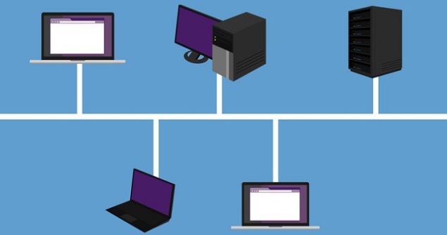
- Both ends of the shared channel have line terminator. The data is sent in only one direction and as soon as it reaches the extreme end, the terminator removes the data from the line.
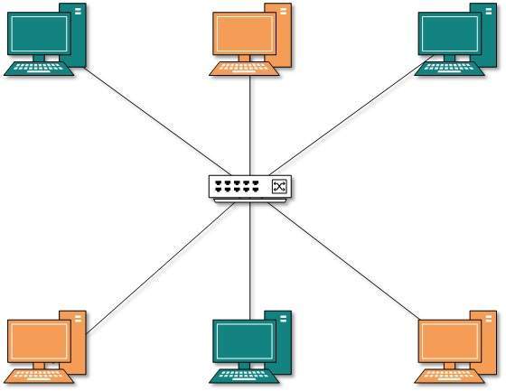
Star Topology
All hosts in Star topology are connected to a central device, known as hub device, using a point-to-point connection. That is, there exists a point to point connection between hosts and hub. The hub device can be any of the following:
- Layer-1 device such as hub or repeater
- Layer-2 device such as switch or bridge
- Layer-3 device such as router or gateway
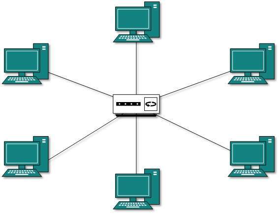
- As in Bus topology, hub acts as single point of failure. If hub fails, connectivity of all hosts to all other hosts fails. Every communication between hosts, takes place through only the hub.
- Star topology is not expensive as to connect one more host, only one cable is required and configuration is simple.
Ring Topology
- In ring topology, each host machine connects to exactly two other machines, creating a circular network structure. When one host tries to communicate or send message to a host which is not adjacent to it, the data travels through all intermediate hosts. To connect one more host in the existing structure, the administrator may need only one more extra cable.
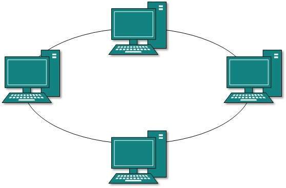
Failure of any host results in failure of the whole ring.Thus, every connection in the ring is a point of failure. There are methods which employ one more backup ring.
Mesh Topology
In this type of topology, a host is connected to one or multiple hosts.This topology has hosts in point-to-point connection with every other host or may also have hosts which are in point-to-point connection to few hosts only.
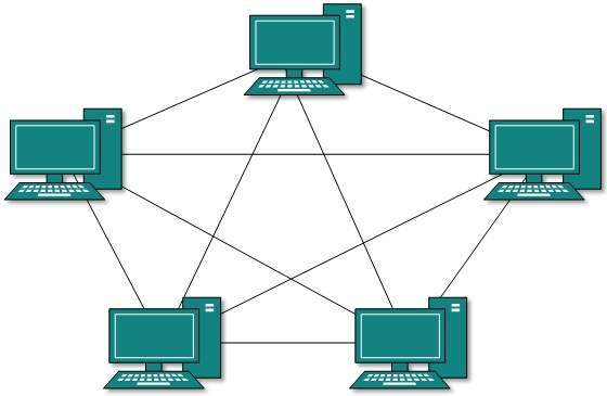
Hosts in Mesh topology also work as relay for other hosts which do not have direct point-to-point links. Mesh technology comes into two types:
Full Mesh- All hosts have a point-to-point connection to every other host in the network. Thus for every new host n(n-1)/2 connections are required. It provides the most reliable network structure among all network topologies.
- Not all hosts have point-to-point connection to every other host. Hosts connect to each other in some arbitrarily fashion. This topology exists where we need to provide reliability to some hosts out of all.
Tree Topology
- Also known as Hierarchical Topology, this is the most common form of network topology in use presently.This topology imitates as extended Star topology and inherits properties of bus topology.
- This topology divides the network in to multiple levels/layers of network. Mainly in LANs, a network is bifurcated into three types of network devices.
- The lowermost is access-layer where computers are attached. The middle layer is known as distribution layer, which works as mediator between upper layer and lower layer.
- The highest layer is known as core layer, and is central point of the network, i.e. root of the tree from which all nodes fork.
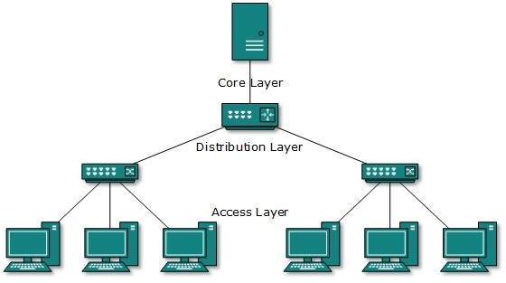
- All neighboring hosts have point-to-point connection between them.Similar to the Bus topology, if the root goes down, then the entire network suffers even.though it is not the single point of failure.
- Every connection serves as point of failure, failing of which divides the network into unreachable segment.
Daisy Chain
- This topology connects all the hosts in a linear fashion. Similar to Ring topology, all hosts are connected to two hosts only, except the end hosts.
- Means, if the end hosts in daisy chain are connected then it represents Ring topology.

- Each link in daisy chain topology represents single point of failure. Every link failure splits the network into two segments.Every intermediate host works as relay for its immediate hosts.
Hybrid Topology
- A network structure whose design contains more than one topology is said to be hybrid topology. Hybrid topology inherits merits and demerits of all the incorporating topologies.
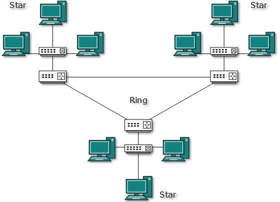
- The above picture represents an arbitrarily hybrid topology.
- The combining topologies may contain attributes of Star, Ring, Bus, and Daisy-chain topologies.
- Most WANs are connected by means of Dual-Ring topology and networks connected to them are mostly Star topology networks.
- Internet is the best example of largest Hybrid topology
Computer Network Models
- Networking engineering is a complicated task, which involves software, firmware, chip level engineering, hardware, and electric pulses.
- To ease network engineering, the whole networking concept is divided into multiple layers.
- Each layer is involved in some particular task and is independent of all other layers.
- But as a whole, almost all networking tasks depend on all of these layers. Layers share data between them and they depend on each other only to take input and send output.
Layered Tasks
- In layered architecture of Network Model, one whole network process is divided into small tasks. Each small task is then assigned to a particular layer which works dedicated to process the task only. Every layer does only specific work.
- In layered communication system, one layer of a host deals with the task done by or to be done by its peer layer at the same level on the remote host.
- The task is either initiated by layer at the lowest level or at the top most level. If the task is initiated by the-top most layer, it is passed on to the layer below it for further processing.
- The lower layer does the same thing, it processes the task and passes on to lower layer. If the task is initiated by lower most layer, then the reverse path is taken.
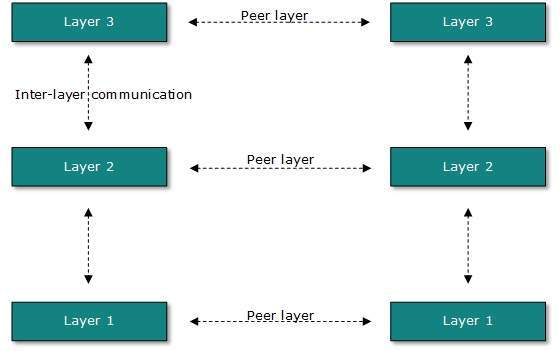
- Every layer clubs together all procedures, protocols, and methods which it requires to execute its piece of task. All layers identify their counterparts by means of encapsulation header and tail.
OSI Model
- Open System Interconnect is an open standard for all communication systems.
- OSI model is established by International Standard Organization (ISO). This model has seven layers:
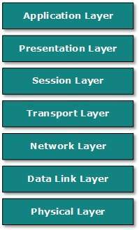
Application Layer:
- This layer is responsible for providing interface to the application user. This layer encompasses protocols which directly interact with the user.
- This layer defines how data in the native format of remote host should be presented in the native format of host.
- This layer maintains sessions between remote hosts. For example, once user/password authentication is done, the remote host maintains this session for a while and does not ask for authentication again in that time span.
- This layer is responsible for end-to-end delivery between hosts.
- This layer is responsible for address assignment and uniquely addressing hosts in a network.
- This layer is responsible for reading and writing data from and onto the line. Link errors are detected at this layer.
- This layer defines the hardware, cabling wiring, power output, pulse rate etc.
Internet Model
- Internet uses TCP/IP protocol suite, also known as Internet suite. This defines Internet Model which contains four layered architecture.
- OSI Model is general communication model but Internet Model is what the internet uses for all its communication.
- The internet is independent of its underlying network architecture so is its Model. This model has the following layers:
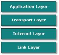
Application Layer:
- This layer defines the protocol which enables user to interact with the network.For example, FTP, HTTP etc.
- This layer defines how data should flow between hosts.
- Major protocol at this layer is Transmission Control Protocol (TCP). This layer ensures data delivered between hosts is in-order and is responsible for end-to-end delivery.
- Internet Protocol (IP) works on this layer. This layer facilitates host addressing and recognition. This layer defines routing.
- This layer provides mechanism of sending and receiving actual data.Unlike its OSI Model counterpart, this layer is independent of underlying network architecture and hardware.
Computer Network Security
- During initial days of internet, its use was limited to military and universities for research and development purpose. Later when all networks merged together and formed internet, the data used to travel through public transit network.Common people may send the data that can be highly sensitive such as their bank credentials, username and passwords, personal documents, online shopping details, or confidential documents.
- All security threats are intentional i.e. they occur only if intentionally triggered. Security threats can be divided into the following categories:
Interruption
- Interruption is a security threat in which availability of resources is attacked. For example, a user is unable to access its web-server or the web-server is hijacked.
Privacy-Breach
- In this threat, the privacy of a user is compromised. Someone, who is not the authorized person is accessing or intercepting data sent or received by the original authenticated user.
Integrity
- This type of threat includes any alteration or modification in the original context of communication.
- The attacker intercepts and receives the data sent by the sender and the attacker then either modifies or generates false data and sends to the receiver.
- The receiver receives the data assuming that it is being sent by the original Sender.
Authenticity
- This threat occurs when an attacker or a security violator, poses as a genuine person and accesses the resources or communicates with other genuine users.
- No technique in the present world can provide 100% security. But steps can be taken to secure data while it travels in unsecured network or internet.
- The most widely used technique is Cryptography.
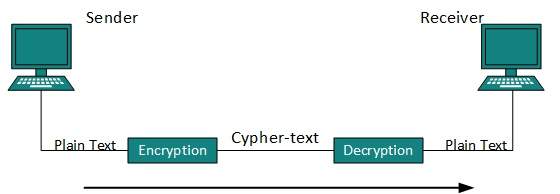
- Cryptography is a technique to encrypt the plain-text data which makes it difficult to understand and interpret. There are several cryptographic algorithms available present day as described below:
- Secret Key
- Public Key
- Message Digest
Secret Key Encryption
- Both sender and receiver have one secret key. This secret key is used to encrypt the data at sender’s end.
- After the data is encrypted, it is sent on the public domain to the receiver. Because the receiver knows and has the Secret Key, the encrypted data packets can easily be decrypted.
- Example of secret key encryption is Data Encryption Standard (DES). In Secret Key encryption, it is required to have a separate key for each host on the network making it difficult to manage.
Public Key Encryption
- In this encryption system, every user has its own Secret Key and it is not in the shared domain. The secret key is never revealed on public domain.
- Along with secret key, every user has its own but public key. Public key is always made public and is used by Senders to encrypt the data.
- When the user receives the encrypted data, he can easily decrypt it by using its own Secret Key.
- Example of public key encryption is Rivest-Shamir-Adleman (RSA).
Message Digest
- In this method, actual data is not sent, instead a hash value is calculated and sent. The other end user, computes its own hash value and compares with the one just received.If both hash values are matched, then it is accepted otherwise rejected.
- Example of Message Digest is MD5 hashing. It is mostly used in authentication where user password is cross checked with the one saved on the server.
Physical Layer - Introduction
- Physical layer in the OSI model plays the role of interacting with actual hardware and signaling mechanism.
- Physical layer is the only layer of OSI network model which actually deals with the physical connectivity of two different stations.
- This layer defines the hardware equipment, cabling, wiring, frequencies, pulses used to represent binary signals etc.
- Physical layer provides its services to Data-link layer. Data-link layer hands over frames to physical layer.
- Physical layer converts them to electrical pulses, which represent binary data.The binary data is then sent over the wired or wireless media.
Signals
- When data is sent over physical medium, it needs to be first converted into electromagnetic signals.
- Data itself can be analog such as human voice, or digital such as file on the disk.Both analog and digital data can be represented in digital or analog signals.
Digital Signals
- Digital signals are discrete in nature and represent sequence of voltage pulses. Digital signals are used within the circuitry of a computer system.
Analog Signals
- Analog signals are in continuous wave form in nature and represented by continuous electromagnetic waves.
Transmission Impairment
When signals travel through the medium they tend to deteriorate. This may have many reasons as given:
Attenuation
- For the receiver to interpret the data accurately, the signal must be sufficiently strong.When the signal passes through the medium, it tends to get weaker.As it covers distance, it loses strength.
Dispersion
- As signal travels through the media, it tends to spread and overlaps. The amount of dispersion depends upon the frequency used.
Delay distortion
- Signals are sent over media with pre-defined speed and frequency. If the signal speed and frequency do not match, there are possibilities that signal reaches destination in arbitrary fashion. In digital media, this is very critical that some bits reach earlier than the previously sent ones.
Noise
- Random disturbance or fluctuation in analog or digital signal is said to be Noise in signal, which may distort the actual information being carried. Noise can be characterized in one of the following class:
Thermal Noise
- Heat agitates the electronic conductors of a medium which may introduce noise in the media. Up to a certain level, thermal noise is unavoidable.
Inter-modulation
- When multiple frequencies share a medium, their interference can cause noise in the medium.
- Inter-modulation noise occurs if two different frequencies are sharing a medium and one of them has excessive strength or the component itself is not functioning properly, then the resultant frequency may not be delivered as expected.
Cross-talk
- This sort of noise happens when a foreign signal enters into the media. This is because signal in one medium affects the signal of second medium.
Impulse
- This noise is introduced because of irregular disturbances such as lightening, electricity, short-circuit, or faulty components. Digital data is mostly affected by this sort of noise.
Transmission Media
- The media over which the information between two computer systems is sent, called transmission media. Transmission media comes in two forms.
Guided Media
- All communication wires/cables are guided media, such as UTP, coaxial cables, and fiber Optics.
- In this media, the sender and receiver are directly connected and the information is send (guided) through it.
Unguided Media
- Wireless or open air space is said to be unguided media, because there is no connectivity between the sender and receiver.
- Information is spread over the air, and anyone including the actual recipient may collect the information.
Channel Capacity
The speed of transmission of information is said to be the channel capacity. We count it as data rate in digital world. It depends on numerous factors such as:
- Bandwidth: The physical limitation of underlying media.
- Error-rate: Incorrect reception of information because of noise.
- Encoding: The number of levels used for signaling.
Multiplexing
- Multiplexing is a technique to mix and send multiple data streams over a single medium.
- This technique requires system hardware called multiplexer (MUX) for multiplexing the streams and sending them on a medium, and de-multiplexer (DMUX) which takes information from the medium and distributes to different destinations.
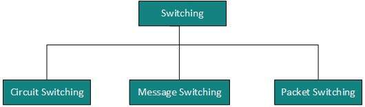
Switching
- Switching is a mechanism by which data/information sent from source towards destination which are not directly connected.
- Networks have interconnecting devices, which receives data from directly connected sources, stores data, analyze it and then forwards to the next interconnecting device closest to the destination.
- Switching can be categorized as:
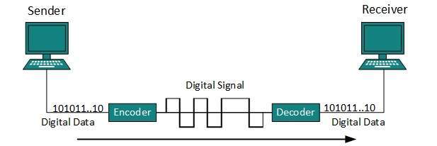
Digital Transmission
- Data or information can be stored in two ways, analog and digital. For a computer to use the data, it must be in discrete digital form.
- Similar to data, signals can also be in analog and digital form. To transmit data digitally, it needs to be first converted to digital form.
Digital-to-Digital Conversion
- This section explains how to convert digital data into digital signals. It can be done in two ways, line coding and block coding.
- For all communications, line coding is necessary whereas block coding is optional.
Line Coding
- The process for converting digital data into digital signal is said to be Line Coding.
- Digital data is found in binary format.It is represented (stored) internally as series of 1s and 0s.
- Digital signal is denoted by discreet signal, which represents digital data.There are three types of line coding schemes available:
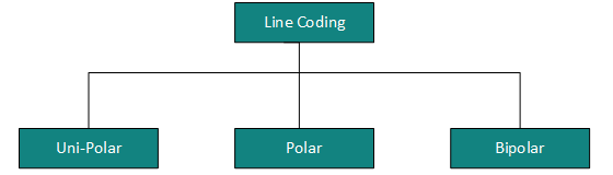
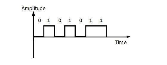
Uni-polar Encoding
- Unipolar encoding schemes use single voltage level to represent data. In this case, to represent binary 1, high voltage is transmitted and to represent 0, no voltage is transmitted.
- It is also called Unipolar-Non-return-to-zero, because there is no rest condition i.e. it either represents 1 or 0.
Polar Encoding
Polar encoding scheme uses multiple voltage levels to represent binary values. Polar encoding is available in four types:
Polar Non-Return to Zero (Polar NRZ)
- It uses two different voltage levels to represent binary values. Generally, positive voltage represents 1 and negative value represents 0. It is also NRZ because there is no rest condition.
- NRZ scheme has two variants: NRZ-L and NRZ-I.
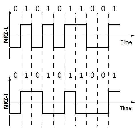
- NRZ-L changes voltage level at when a different bit is encountered whereas NRZ-I changes voltage when a 1 is encountered.
Return to Zero (RZ)
- Problem with NRZ is that the receiver cannot conclude when a bit ended and when the next bit is started, in case when sender and receiver’s clock are not synchronized.
- RZ uses three voltage levels, positive voltage to represent 1, negative voltage to represent 0 and zero voltage for none. Signals change during bits not between bits.
Manchester
- This encoding scheme is a combination of RZ and NRZ-L. Bit time is divided into two halves.
- It transits in the middle of the bit and changes phase when a different bit is encountered.
Differential Manchester
- This encoding scheme is a combination of RZ and NRZ-I. It also transit at the middle of the bit but changes phase only when 1 is encountered.
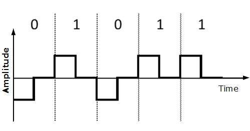
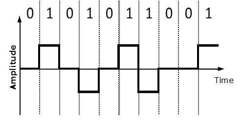
Bipolar Encoding
- Bipolar encoding uses three voltage levels, positive, negative and zero. Zero voltage represents binary 0 and bit 1 is represented by altering positive and negative voltages.
Block Coding
- To ensure accuracy of the received data frame redundant bits are used. For example, in even-parity, one parity bit is added to make the count of 1s in the frame even.
- This way the original number of bits is increased. It is called Block Coding.
- Block coding is represented by slash notation, mB/nB.
- Means, m-bit block is substituted with n-bit block where n > m. Block coding involves three steps:
- Division,
- Substitution
- Combination.
After block coding is done, it is line coded for transmission.
Analog-to-Digital Conversion
- Microphones create analog voice and camera creates analog videos, which are treated is analog data.
- To transmit this analog data over digital signals, we need analog to digital conversion.
- Analog data is a continuous stream of data in the wave form whereas digital data is discrete.
- To convert analog wave into digital data, we use Pulse Code Modulation (PCM).
- PCM is one of the most commonly used method to convert analog data into digital form. It involves three steps:
- Sampling
- Quantization
- Encoding.
Sampling
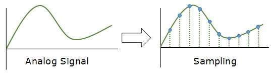
- The analog signal is sampled every T interval. Most important factor in sampling is the rate at which analog signal is sampled.
- According to Nyquist Theorem, the sampling rate must be at least two times of the highest frequency of the signal.
Quantization
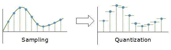
- Sampling yields discrete form of continuous analog signal. Every discrete pattern shows the amplitude of the analog signal at that instance.
- The quantization is done between the maximum amplitude value and the minimum amplitude value. Quantization is approximation of the instantaneous analog value.
Encoding
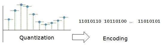
In encoding, each approximated value is then converted into binary format.
Transmission Modes
- The transmission mode decides how data is transmitted between two computers.The binary data in the form of 1s and 0s can be sent in two different modes: Parallel and Serial.
Parallel Transmission
- The binary bits are organized in-to groups of fixed length. Both sender and receiver are connected in parallel with the equal number of data lines.
- Both computers distinguish between high order and low order data lines.
- The sender sends all the bits at once on all lines.Because the data lines are equal to the number of bits in a group or data frame, a complete group of bits (data frame) is sent in one go.
- Advantage of Parallel transmission is high speed and disadvantage is the cost of wires, as it is equal to the number of bits sent in parallel.
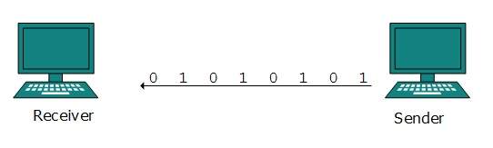
Serial Transmission
- In serial transmission, bits are sent one after another in a queue manner. Serial transmission requires only one communication channel.
- Serial transmission can be either asynchronous or synchronous.
Asynchronous Serial Transmission
- It is named so because there’is no importance of timing. Data-bits have specific pattern and they help receiver recognize the start and end data bits.
- For example, a 0 is prefixed on every data byte and one or more 1s are added at the end.
- Two continuous data-frames (bytes) may have a gap between them.
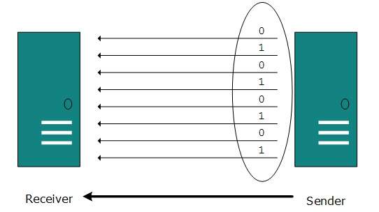
Synchronous Serial Transmission
- Timing in synchronous transmission has importance as there is no mechanism followed to recognize start and end data bits.
- There is no pattern or prefix/suffix method. Data bits are sent in burst mode without maintaining gap between bytes (8-bits).
- Single burst of data bits may contain a number of bytes. Therefore, timing becomes very important.
- It is up to the receiver to recognize and separate bits into bytes.
- The advantage of synchronous transmission is high speed, and it has no overhead of extra header and footer bits as in asynchronous transmission.
Analog Transmission
- To send the digital data over an analog media, it needs to be converted into analog signal.There can be two cases according to data formatting.
Band-pass:
- The filters are used to filter and pass frequencies of interest. A band-pass is a band of frequencies which can pass the filter.
Low-pass:
- Low-pass is a filter that passes low frequencies signals.
- When digital data is converted into a band-pass analog signal, it is called digital-to-analog conversion.
- When low-pass analog signal is converted into band-pass analog signal, it is called analog-to-analog conversion.
Digital-to-Analog Conversion
- When data from one computer is sent to another via some analog carrier, it is first converted into analog signals. Analog signals are modified to reflect digital data.
- An analog signal is characterized by its amplitude, frequency, and phase. There are three kinds of digital-to-analog conversions:
Amplitude Shift Keying
- In this conversion technique, the amplitude of analog carrier signal is modified to reflect binary data.
- When binary data represents digit 1, the amplitude is held; otherwise it is set to 0. Both frequency and phase remain same as in the original carrier signal.
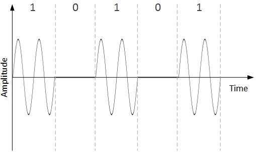
Frequency Shift Keying
- In this conversion technique, the frequency of the analog carrier signal is modified to reflect binary data.
- This technique uses two frequencies, f1 and f2. One of them, for example f1, is chosen to represent binary digit 1 and the other one is used to represent binary digit 0.
- Both amplitude and phase of the carrier wave are kept intact.
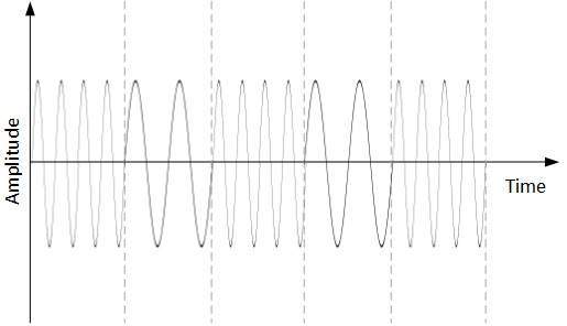
Phase Shift Keying
- In this conversion scheme, the phase of the original carrier signal is altered to reflect the binary data.
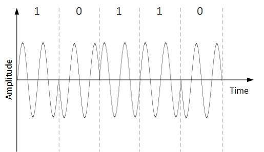
- When a new binary symbol is encountered, the phase of the signal is altered.
- Amplitude and frequency of the original carrier signal is kept intact.
Quadrature Phase Shift Keying
- QPSK alters the phase to reflect two binary digits at once. This is done in two different phases. The main stream of binary data is divided equally into two sub-streams.
- The serial data is converted in to parallel in both sub-streams and then each stream is converted to digital signal using NRZ technique.
- Later, both the digital signals are merged together.
Analog-to-Analog Conversion
- Analog signals are modified to represent analog data. This conversion is also known as Analog Modulation.
- Analog modulation is required when band-pass is used. Analog to analog conversion can be done in three ways:
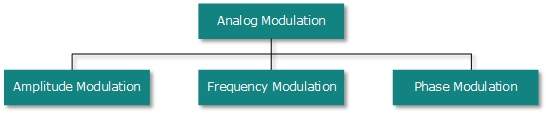
Amplitude Modulation
- In this modulation, the amplitude of the carrier signal is modified to reflect the analog data.
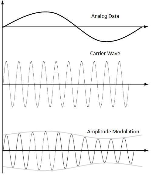
- Amplitude modulation is implemented by means of a multiplier.
- The amplitude of modulating signal (analog data) is multiplied by the amplitude of carrier frequency, which then reflects analog data.
- The frequency and phase of carrier signal remain unchanged.
Frequency Modulation
- In this modulation technique, the frequency of the carrier signal is modified to reflect the change in the voltage levels of the modulating signal (analog data).
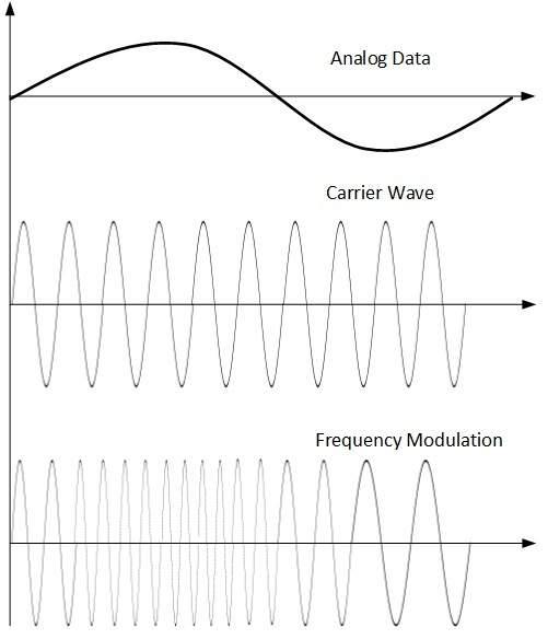
- The amplitude and phase of the carrier signal are not altered.
Phase Modulation
- In the modulation technique, the phase of carrier signal is modulated in order to reflect the change in voltage (amplitude) of analog data signal.
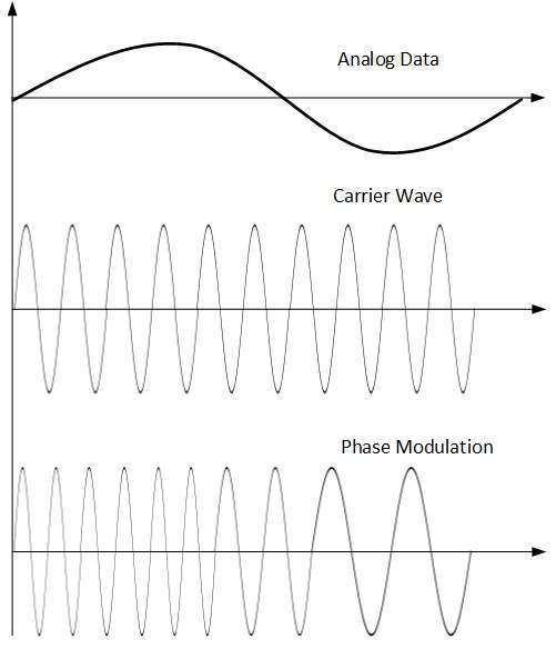
- Phase modulation is practically similar to Frequency Modulation, but in Phase modulation frequency of the carrier signal is not increased.
- Frequency of carrier is signal is changed (made dense and sparse) to reflect voltage change in the amplitude of modulating signal.
Transmission Media
- The transmission media is nothing but the physical media over which communication takes place in computer networks.
Magnetic Media
- One of the most convenient way to transfer data from one computer to another, even before the birth of networking, was to save it on some storage media and transfer physical from one station to another.
- Though it may seem old-fashion way in today’s world of high speed internet, but when the size of data is huge, the magnetic media comes into play.
- For example, a bank has to handle and transfer huge data of its customer, which stores a backup of it at some geographically far-away place for security reasons and to keep it from uncertain calamities.
- If the bank needs to store its huge backup data then its,transfer through internet is not feasible.
- The WAN links may not support such high speed.Even if they do; the cost too high to afford.
- In these cases, data backup is stored onto magnetic tapes or magnetic discs, and then shifted physically at remote places.
Twisted Pair Cable
- A twisted pair cable is made of two plastic insulated copper wires twisted together to form a single media.
- Out of these two wires, only one carries actual signal and another is used for ground reference.
- The twists between wires are helpful in reducing noise (electro-magnetic interference) and crosstalk.

There are two types of twisted pair cables:
- Shielded Twisted Pair (STP) Cable
- Unshielded Twisted Pair (UTP) Cable
- STP cables comes with twisted wire pair covered in metal foil. This makes it more indifferent to noise and crosstalk.
- UTP has seven categories, each suitable for specific use. In computer networks, Cat-5, Cat-5e, and Cat-6 cables are mostly used. UTP cables are connected by RJ45 connectors.
Coaxial Cable
- Coaxial cable has two wires of copper. The core wire lies in the center and it is made of solid conductor.
- The core is enclosed in an insulating sheath.The second wire is wrapped around over the sheath and that too in turn encased by insulator sheath.This all is covered by plastic cover.
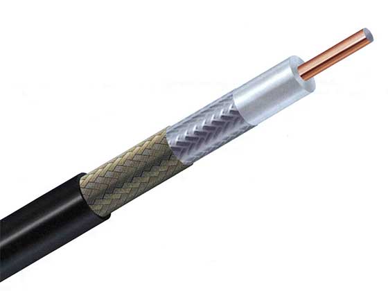
- Because of its structure,the coax cable is capable of carrying high frequency signals than that of twisted pair cable.
- The wrapped structure provides it a good shield against noise and cross talk. Coaxial cables provide high bandwidth rates of up to 450 mbps.
- There are three categories of coax cables namely, RG-59 (Cable TV), RG-58 (Thin Ethernet), and RG-11 (Thick Ethernet). RG stands for Radio Government.
- Cables are connected using BNC connector and BNC-T. BNC terminator is used to terminate the wire at the far ends.
Power Lines
- Power Line communication (PLC) is Layer-1 (Physical Layer) technology which uses power cables to transmit data signals.In PLC, modulated data is sent over the cables.
- The receiver on the other end de-modulates and interprets the data.
- Because power lines are widely deployed, PLC can make all powered devices controlled and monitored. PLC works in half-duplex.
- There are two types of PLC:
- Narrow band PLC
- Broad band PLC
- Narrow band PLC provides lower data rates up to 100s of kbps, as they work at lower frequencies (3-5000 kHz).They can be spread over several kilometers.
- Broadband PLC provides higher data rates up to 100s of Mbps and works at higher frequencies (1.8 – 250 MHz).They cannot be as much extended as Narrow-band PLC.
Fiber Optics
- Fiber Optic works on the properties of light. When light ray hits at critical angle it tends to refracts at 90 degree.
- This property has been used in fiber optic.
- The core of fiber optic cable is made of high quality glass or plastic.
- From one end of it light is emitted, it travels through it and at the other end light detector detects light stream and converts it to electric data.
- Fiber Optic provides the highest mode of speed. It comes in two modes, one is single mode fiber and second is multimode fiber.
- Single mode fiber can carry a single ray of light whereas multimode is capable of carrying multiple beams of light.
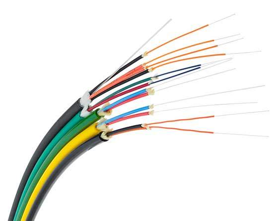
- Fiber Optic also comes in unidirectional and bidirectional capabilities. To connect and access fiber optic special type of connectors are used. These can be Subscriber Channel (SC), Straight Tip (ST), or MT-RJ.
Wireless Transmission
- Wireless transmission is a form of unguided media. Wireless communication involves no physical link established between two or more devices, communicating wirelessly.
- Wireless signals are spread over in the air and are received and interpreted by appropriate antennas.
- When an antenna is attached to electrical circuit of a computer or wireless device, it converts the digital data into wireless signals and spread all over within its frequency range.
- The receptor on the other end receives these signals and converts them back to digital data.
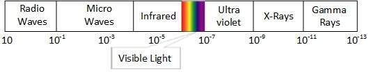
- A little part of electromagnetic spectrum can be used for wireless transmission.
Radio Transmission
- Radio frequency is easier to generate and because of its large wavelength it can penetrate through walls and structures alike.Radio waves can have wavelength from 1 mm – 100,000 km and have frequency ranging from 3 Hz (Extremely Low Frequency) to 300 GHz (Extremely High Frequency).
- Radio frequencies are sub-divided into six bands.
- Radio waves at lower frequencies can travel through walls whereas higher RF can travel in straight line and bounce back.
- The power of low frequency waves decreases sharply as they cover long distance. High frequency radio waves have more power.
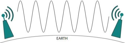
- Lower frequencies such as VLF, LF, MF bands can travel on the ground up to 1000 kilometers, over the earth’s surface.
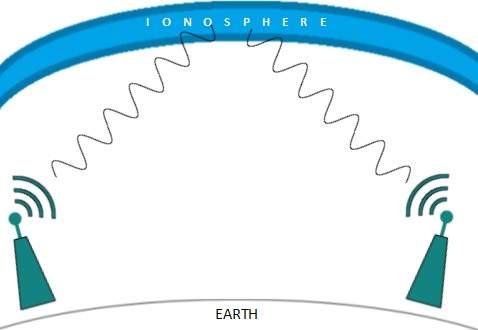
- Radio waves of high frequencies are prone to be absorbed by rain and other obstacles. They use Ionosphere of earth atmosphere.
- High frequency radio waves such as HF and VHF bands are spread upwards. When they reach Ionosphere, they are refracted back to the earth.
Microwave Transmission
- Electromagnetic waves above 100 MHz tend to travel in a straight line and signals over them can be sent by beaming those waves towards one particular station.
- Because Microwaves travels in straight lines, both sender and receiver must be aligned to be strictly in line-of-sight.
- Microwaves can have wavelength ranging from 1 mm – 1 meter and frequency ranging from 300 MHz to 300 GHz.
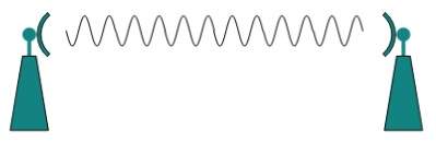
- Microwave antennas concentrate the waves making a beam of it. As shown in picture above, multiple antennas can be aligned to reach farther.
- Microwaves have higher frequencies and do not penetrate wall like obstacles.
- Microwave transmission depends highly upon the weather conditions and the frequency it is using.
Infrared Transmission
- Infrared wave lies in between visible light spectrum and microwaves. It has wavelength of 700-nm to 1-mm and frequency ranges from 300-GHz to 430-THz.
- Infrared wave is used for very short range communication purposes such as television and it’s remote.
- Infrared travels in a straight line hence it is directional by nature. Because of high frequency range, Infrared cannot cross wall-like obstacles.
Light Transmission
- Highest most electromagnetic spectrum which can be used for data transmission is light or optical signaling. This is achieved by means of LASER.
- Because of frequency light uses, it tends to travel strictly in straight line.Hence the sender and receiver must be in the line-of-sight.
- Because laser transmission is unidirectional, at both ends of communication the laser and the photo-detector needs to be installed.
- Laser beam is generally 1mm wide hence it is a work of precision to align two far receptors each pointing to lasers source.
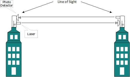
- Laser works as Tx (transmitter) and photo-detectors works as Rx (receiver).
- Lasers cannot penetrate obstacles such as walls, rain, and thick fog.
- Additionally, laser beam is distorted by wind, atmosphere temperature, or variation in temperature in the path.
- Laser is safe for data transmission as it is very difficult to tap 1mm wide laser without interrupting the communication channel.
Multiplexing
- Multiplexing is a technique by which different analog and digital streams of transmission can be simultaneously processed over a shared link.
- Multiplexing divides the high capacity medium into low capacity logical medium which is then shared by different streams.
- Communication is possible over the air (radio frequency), using a physical media (cable), and light (optical fiber). All mediums are capable of multiplexing.
- When multiple senders try to send over a single medium, a device called Multiplexer divides the physical channel and allocates one to each.
- On the other end of communication, a De-multiplexer receives data from a single medium, identifies each, and sends to different receivers.
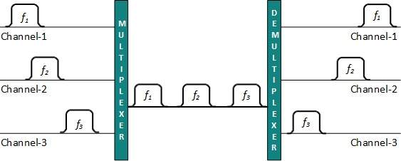
Frequency Division Multiplexing
- When the carrier is frequency, FDM is used. FDM is an analog technology.
- FDM divides the spectrum or carrier bandwidth in logical channels and allocates one user to each channel.
- Each user can use the channel frequency independently and has exclusive access of it. All channels are divided in such a way that they do not overlap with each other.
- Channels are separated by guard bands. Guard band is a frequency which is not used by either channel.
Time Division Multiplexing
- TDM is applied primarily on digital signals but can be applied on analog signals as well.
- In TDM the shared channel is divided among its user by means of time slot. Each user can transmit data within the provided time slot only.
- Digital signals are divided in frames, equivalent to time slot i.e. frame of an optimal size which can be transmitted in given time slot.
- TDM works in synchronized mode. Both ends, i.e. Multiplexer and De-multiplexer are timely synchronized and both switch to next channel simultaneously.
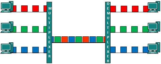
- When channel A transmits its frame at one end,the De-multiplexer provides media to channel A on the other end.As soon as the channel A’s time slot expires, this side switches to channel B.
- On the other end, the De-multiplexer works in a synchronized manner and provides media to channel B.
- Signals from different channels travel the path in interleaved manner.
Wavelength Division Multiplexing
- Light has different wavelength (colors). In fiber optic mode, multiple optical carrier signals are multiplexed into an optical fiber by using different wavelengths.
- This is an analog multiplexing technique and is done conceptually in the same manner as FDM but uses light as signals.
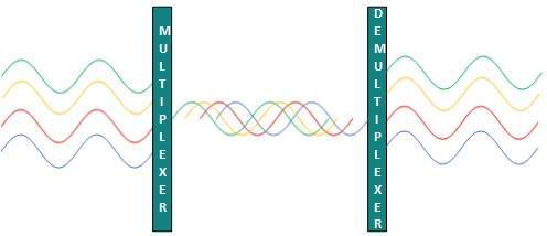
- Further, on each wavelength time division multiplexing can be incorporated to accommodate more data signals.
Code Division Multiplexing
- Multiple data signals can be transmitted over a single frequency by using Code Division Multiplexing.
- FDM divides the frequency in smaller channels but CDM allows its users to full bandwidth and transmit signals all the time using a unique code.
- CDM uses orthogonal codes to spread signals.
- Each station is assigned with a unique code, called chip. Signals travel with these codes independently, inside the whole bandwidth.
- The receiver knows in advance the chip code signal it has to receive.


Very helpful guide! I was stuck with errors for hours, and your breakdown finally made sense of it. The step-by-step tips are easy to follow, especially for beginners dealing with Switch setups. For anyone else running into issues like tinfoil could not start the software, this resource is a lifesaver. Thanks for sharing!
ReplyDelete